Understanding Logic Gates and DeMorgan's Theorems in Computer Systems

Exploring the concepts of logic gates, truth tables, and DeMorgan's Theorems in computer systems. Learn about how Boolean algebra is used to analyze digital gates and circuits, the functions of Negative-AND and Negative-OR gates, and how DeMorgan's First and Second Theorems are applied through truth tables. Understand the equivalence between NAND and NOR gates with bubbled OR and AND gates respectively.

Download Presentation

Please find below an Image/Link to download the presentation.
The content on the website is provided AS IS for your information and personal use only. It may not be sold, licensed, or shared on other websites without obtaining consent from the author. Download presentation by click this link. If you encounter any issues during the download, it is possible that the publisher has removed the file from their server.
E N D
Presentation Transcript
COMPUTER SYSTEM AND ORGANISATION (MODULE 6/6) BY Mrs. SUJATA PRADHAN PGT(SS),AECS,ANUPURAM
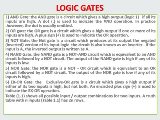
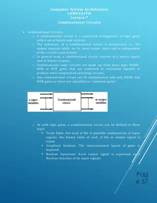
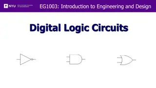
Logic Gates & Truth Tables Boolean Algebra is the mathematics used to analyse digital gates and circuits.
Negative AND & Negative OR gate A B A B A .B A B A B A +B 0 0 1 1 1 0 0 1 1 1 0 1 1 0 1 0 1 1 0 0 1 0 0 1 1 1 0 0 1 0 1 1 0 0 0 1 1 0 0 0 A Negative-AND gate, functions the same as an AND gate with all its inputs inverted (connected through NOT gates). A Negative-OR gate , functions the same as an OR gate with all its inputs inverted. Keeping standard gate symbol convention, these inverted inputs are signified by bubbles. So negative AND gate and Negative OR gates are also called as Bubbled AND and Bubbled OR gates respectively.
DeMorgans First Theorem According to De Morgan s theorem, a NANDgate is equivalent to a bubbled OR gate. Therefore, the equation can be written as shown below. The Boolean expressions for NAND gate is The Boolean expressions for the bubbled OR gate is As the NAND and bubbled OR gates are interchangeable, i.e., both gates have exactly identical outputs for the same set of inputs.
Evaluation of DeMorgansTheorem using Truth Table Prove (X.Y) = X +Y using truth table. X Y X.Y (X.Y) X Y X +Y 0 0 0 1 1 1 1 0 1 0 1 1 0 1 1 0 0 1 0 1 1 1 1 1 0 0 0 0 From Truth Table it is proved that columns (X.Y) = X +Y
DeMorgans Second Theorem According to DeMorgan s theorem, a NOR gate is equivalent to a bubbled AND gate. Therefore, the equation can be written as shown below The Boolean equation for the bubbled AND gate is The Boolean equation for NOR gate is As the NOR and bubbled AND gates are interchangeable, i.e., both gates have exactly identical outputs for the same set of inputs.
DeMorgansTheorem using Truth Table Prove (X+Y) = X .Y using truth table. X Y X+Y (X+Y) X Y X .Y 0 0 0 1 1 1 1 0 1 1 0 1 0 0 1 0 1 0 0 1 0 1 1 1 0 0 0 0 From Truth Table it is proved that columns (X+Y) = X .Y
Boolean equations of De Morgans Theorem Note: When a long bar is broken, the operation directly underneath the break changes from logical AND operation to logical OR operation and vice versa.
Universal Gates In addition to AND, OR, and NOT ,fundamental gates, other logic gates like NAND and NOR are also used in the design of digital circuits. A universal gate is a gate which can implement any Boolean function without use of any other gate type. The NAND and NOR gates are universal gates. In practice, this is advantageous since NAND and NOR gates are economical and easier to fabricate all IC digital logic families. NAND Gate: The NAND gate represents the complement of the AND operation. Its name is an abbreviation of NOT AND. The graphic symbol for the NAND gate consists of an AND symbol with a bubble on the output, denoting that a complement operation is perform. NOR Gate: The NOR gate represents the complement of the OR operation. Its name is an abbreviation of NOT OR. The graphic symbol for the NOR gate consists of an OR symbol with a bubble on the output, ed on the output of the AND gate.
Universality of NAND Gates 1. Implementing an Inverter (NOT gate) using only NAND Gate All NAND input pins connect to the input signal A gives an output A . 2. Implementing AND Using only NAND Gates An AND gate can be replaced by two NAND gates as shown in the figure. 3. Implementing OR Using only NAND Gates An OR gate can be replaced by three NAND gates as shown in the figure . Thus, the NAND gate is a universal gate since it can implement the AND, OR and NOT.
Universality of NOR Gates Implementing an Inverter Using only NOR Gate: All NOR input pins connect to the input signal A gives an output A . Implementing OR Using only NOR Gates: An OR gate can be replaced by NOR gates as shown in the figure (The OR is replaced by a NOR gate with its output complemented by a NOR gate inverter) Implementing AND Using only NOR Gates: An AND gate can be replaced by NOR gates as shown in the figure (The AND gate is replaced by a NOR gate with all its inputs complemented by NOR gate inverters) Thus, the NOR gate is a universal gate since it can implement the AND, OR and NOT functions
Boolean Equation of XOR and XNOR Gates Boolean Equation of XOR F(A,B)=A .B+A.B Boolean Equation of XNOR F(A,B)=A.B+A .B Like truth tables,it can be proved algebraically (XOR) =XNOR F(A,B)= (A .B+A.B ) =(A .B) . (A.B ) =((A ) + B ) . (A + (B ) ) =(A + B ) . (A + B) =A.A + A.B +B .A + B .B =A.B + A .B Hence proved (De Morgan s Theorem) (De Morgan s Theorem) ((A ) =A) (A.A =B.B =0)
Simplification of Boolean Function A B A.B A+B (A+B) A.B+(A+B) 0 0 0 0 1 1 0 1 0 1 0 0 1 0 0 1 0 0 1 1 1 1 0 1 Then, the whole circuit above can be replaced by just one single Exclusive-NOR Gate and indeed an Exclusive-NOR Gate is made up of these individual gate functions. A.B + (A+B) = A.B + A .B (Use De Morgan s Theorem)
Minimization of Boolean Functions we need to apply the rules of Boolean algebra to reduce the expression to its simplest form. Minimized version of the Boolean Expression needs less number of logic gates and also reduces the complexity of the circuit substantially. Hence minimization is important to find the most economic equivalent representation of a boolean function. The component reduction results in higher operating speed, less power consumption, less cost, and greater reliability. Example: F(X,Y,Z) = X Y Z + X Y Z + X Y = X Z ( Y + Y ) + X Y = X Z + X Y (Y + Y = 1) = X Y + X Z
Laws of Boolean Algebra Boolean laws can be used to prove any given Boolean expression as well as for simplifying complicated digital circuits. Commutative Law A . B = B . A A + B = B + A Associative Law A . (B . C) = (A . B) . C A . (B . C) = (A . B) . C Distributive Law A + BC = (A + B) (A + C) A . (B+C) = A . B + A . C Annulment law: A.0 = 0 A + 1 = 1 Identity law: A.1 = A A + 0 = A Idempotent law: A + A = A A . A = A Complement law: A + A' = 1 A . A'= 0 Double negation law: (A)')' = A Absorption law: A.(A+B) = A A + AB = A De Morgan s Theorem (A + B) = A . B (A . B) = A + B
SUMMARY De Morgan s Theorem Negative AND & Negative OR Gates Universality of NAND and NOR Gates Boolean Equation from a circuit Simplification of Boolean Functions