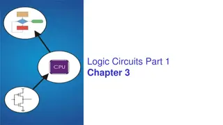
Understanding Logic Circuits in Computer Architecture

Explore the world of logic circuits through this comprehensive guide. Learn about logic gates, truth tables, and how computers are built from these components. Discover the basics of logic gates like AND, OR, and NOT, and delve into connecting gates to create functional circuits. Enhance your understanding by observing circuit-to-truth table mappings and grasp how these circuits process information.

Download Presentation

Please find below an Image/Link to download the presentation.
The content on the website is provided AS IS for your information and personal use only. It may not be sold, licensed, or shared on other websites without obtaining consent from the author. Download presentation by click this link. If you encounter any issues during the download, it is possible that the publisher has removed the file from their server.
E N D
Presentation Transcript
TeachingLondon Computing Programming for GCSE Topic 9.1: Logic Circuits William Marsh School of Electronic Engineering and Computer Science Queen Mary University of London
Aims Show how computers are built from logic gates Logic gates and truth tables and boolean algebra Circuit for Adding
Teaching Issue How to provide a coherent, joined up view Some curricula include logic circuits but it is not related to operation of a computer Logic circuits add binary numbers computer architecture
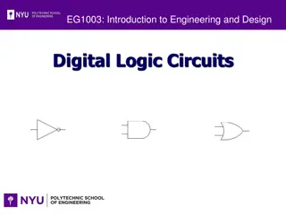
LOGIC GATES And, Or, Not
Logic Gates Logic gates are electronic components Transistors Gates behave like switches Two states State represented by a boolean variable closed, X = 1 open, X = 0
Basic Logic Gates X OR gate X Y Y AND gate X Y X Y
NOT Gate X not X not X Only 1 input X
Basic Logic Gates OR gate NOT gate X X not X Y AND gate X Y
Connecting Gates Output of one gate connects to input for next X0 X1 Y X2
AND, OR True when either X or Y true OR gate X Y X + Y 0 0 0 0 1 1 1 0 1 1 1 1 X Y True when both X and Y true AND gate X Y X . Y 0 0 0 0 1 0 1 0 0 1 1 1 X Y
Circuit to Truth Table X0 X1 Test a circuit Y X2 X2 X1 X0 Y 0 0 0 0 0 1 0 1 0 0 1 1 1 0 0 1 0 1 1 1 0 1 1 1
Circuit to Truth Table X0 X1 Test a circuit Y X2 X2 X1 X0 Y 0 0 0 0 0 0 1 0 0 1 0 0 0 1 1 0 1 0 0 1 0 1 1 1 0 1 1 1
Circuit to Truth Table X0 X1 Test a circuit Y X2 X2 X1 X0 Y 0 0 0 0 0 0 1 0 0 1 0 0 0 1 1 0 1 0 0 0 1 0 1 1 1 1 0 1 1 1 1 1 Two circuits equivalent if (and only if) they have the same truth table
TRANSLATING CIRCUITSTO BOOLEAN ALGEBRA
Circuit to Formula ((X0 or X1)and X2) or not X1 Label each point in turn X0 or X1 (X0 or X1)and X2 X0 X1 X2 not X1
De-Morgan s Laws Recap Important law for exchanging AND with OR A and B is false when either A is false or B is false ( A . B ) = A + B A or B is false when both A is false and B is false ( A + B ) = A . B
De-Morgan s Law II ( A + B ) = A . B Same with circuits A A B B Quiz: draw the other law as a circuit
De-Morgan s Law III ( A . B ) = A + B Second law as a circuits A A B B
Summary Logic circuits Build a computer Truth table Specify a circuit Boolean expression (formula) Algebraic rules All express same thing Translate from one to other