Understanding Digital Logic Circuits: A Comprehensive Overview
Delve into the world of digital logic circuits with a focus on logic gates, truth tables, Boolean equations, and Karnaugh Maps. Explore the concepts of AND, OR, NOT gates, along with practical applications such as ATM machine operations. Gain insights into designing combinational logic circuits and testing them using LabVIEW and NI-ELVIS prototyping board.

Download Presentation

Please find below an Image/Link to download the presentation.
The content on the website is provided AS IS for your information and personal use only. It may not be sold, licensed, or shared on other websites without obtaining consent from the author. Download presentation by click this link. If you encounter any issues during the download, it is possible that the publisher has removed the file from their server.
E N D
Presentation Transcript
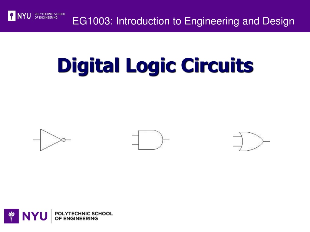
EG1003: Introduction to Engineering and Design Digital Logic Circuits Image:lab_logic_1.jpg Image:lab_logic_4.jpg Image:lab_logic_7.jpg
Overview Objectives Background Materials Procedure Report / Presentation Closing
Objectives Understand logic gates and digital logic circuits Design combinational logic circuit Activate under specific conditions Test with LabVIEW Test using NI-ELVIS prototyping board
Logic Functions AND - All or nothing operator Output high (1) only when ALL inputs are high (1) OR gate - Any or all operator Output high (1) when at least ONE input is high (1) NOT operator Inverter Output always opposite of input Only one input and one output
Logic Functions Truth Table Inputs A B 0 0 0 1 1 0 1 1 0 0 0 1 1 0 1 1 0 - Boolean Expression Output Y 0 0 0 1 0 1 1 1 1 Logic Function Logic Symbol AND A B = Y OR A + B = Y A = NOT 1 - 0
Sample Problem ATM machine has three options: Print statement Withdraw money Deposit money ATM machine will charge $1.00 to: Withdraw Print out statement with no transactions No charge for: Deposits without withdrawal
Truth Table A truth table displays all possible input / output combinations. INPUTS P 0 0 0 0 1 OUTPUT C 0 0 1 1 1 0 1 W 0 0 1 1 D 0 INPUT OUTPUT 1 0 1 P = Print C = Charge W = Withdraw D = Deposit 0 0 1 0 1 0 = do not 0 = $0.00 1 = do 1 = $1.00 1 1 0 1 1 1 1
Boolean Equation Outputs with a value of ONE are kept INPUTS W 0 0 1 1 OUTPUT C 0 0 1 1 1 0 1 D 0 P 0 0 0 0 1 C = PWD 1 0 1 + PWD + PWD 0 0 1 0 1 1 + PWD + PWD 1 0 1 1 1 1
Karnaugh Maps (K-maps) C = PWD+ PWD+ PWD + PWD + PWD PWD PWD PWD 0 1 0 0 1 1 1 0 P W P W 1 P W P W 1 0 1 1 0 1 D D 0 0 1 _ Why can t you switch PW and PW? Why can t you loop the three adjacent 1s in the top row together?
Karnaugh Maps (K-maps) C = PWD+ PWD+ PWD + PWD + PWD 0 0 0 1 1 1 1 0 P W P W 1 P W P W 1 0 1 1 0 1 D D 0 0 1 NOTE:Circle neighboring ONES in powers of 2. Try to find the greatest amount of neighbors. Only overlap circles as a last resort!
Simplified Boolean Equation _ _ PWD _ PWD D D 0 0 Opposite values cancel out P P P W W W W 1 1 _ 1 1 _ _ _ 1 1 1 1 C = W 1 1 PWD 1 0 _ + PD P PWD PWD PWD
Simplified Boolean Equation Opposite values in circles cancel out _ _ PWD _ PWD 1 D D 0 0 3 _ PWD P P P W W W W = W Step 2 PWD 4 1 1 1 1 _ _ 1 0 Step 1 PWD _ _ PWD = PD P C = W + PD
Combinational Logic Circuit W C =W W W W P D _ PD PD PD PD PD + + + + _ D PD
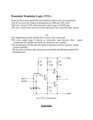
Integrated Circuits (ICs) Used for implementation of combinational logic circuits Use TTL family (transistor transistor logic)
Materials for Lab Computer equipped with LabVIEW NI-ELVIS II+ Prototyping Board DIP Switch Hook-up Wire
Problem Statement A farmer has 2 barns 3 items: fox, hen, corn Items can be in any barn, in any combination Concerns: Protect hen from fox Protect corn from hen Design alarm system using digital electronics. Alarm sounds when: Fox and hen are in same barn Hen and corn are in same barn
Problem Statement Design combination logic circuit for alarm system: Use least amount of gates and input variables (cost effectiveness) Logical circuit output connected to LED LED on indicates alarm activation LED off indicates no problem (alarm off) Fox, hen and corn must be in barn 1 or barn 2 Presence in barn 1 = 1 Presence in barn 2 = 0
Procedure Truth Table Determine input and output variable (s) Truth Table Boolean Expression K-Map Simplified Boolean Expression How many combinations are there? Logic Circuit LabVIEW Simulation Complete truth table on a sheet of paper NI-ELVIS
Procedure Boolean Expression Gather all combinations that produce a 1 for output Truth Table Boolean Expression K-Map Simplified Boolean Expression Create a Boolean expression from these smaller expressions (independent conditions) Logic Circuit LabVIEW Simulation NI-ELVIS
Procedure K-Map Create a K-Map table Truth Table Boolean Expression K-Map Only have one variable change state at a time between adjacent boxes Simplified Boolean Expression Logic Circuit LabVIEW Simulation Use the Boolean expression to fill in the 1 s NI-ELVIS
Procedure Simplified Boolean Expression Use K-Map to circle groups of 1 s Truth Table Boolean Expression K-Map Simplified Boolean Expression 1 s may only be circled in powers of 2, starting from largest possible combination and working downward Logic Circuit LabVIEW Simulation NI-ELVIS Write new simplified expression
Procedure Logic Circuit Diagram Use new simplified Boolean expression to design a logic circuit Truth Table Boolean Expression K-Map Simplified Boolean Expression Have TA check/initial work Logic Circuit LabVIEW Simulation NI-ELVIS
Procedure LabVIEW Simulation Create logic circuit in LabVIEW based on theoretical work Front panel 3 control switches represent input variables 1 Boolean indicator shows output Truth Table Boolean Expression K-Map Simplified Boolean Expression Logic Circuit LabVIEW Simulation HINT: some LabVIEW comparison functions are: NI-ELVIS AND OR NOT
Procedure NI-ELVIS Prototyping Board Do NOT electrically connect anything until TA has reviewed your work Truth Table Boolean Expression K-Map Connect +5V and ground to the DIP switch Use created logic circuit and IC chip diagram to wire actual circuit on the prototyping board Be sure to connect each of the ICs to Ground and +5V (circuit power) Connect final output to an LED. **VCCis an acronym: **Voltage at the Common Collector (+5V) Simplified Boolean Expression Logic Circuit LabVIEW Simulation NI-ELVIS
Assignment: Report Individual Report Title page Discussion topics in the manual Scan in data and lab notes Original tables and work should be legible Include screenshots of LabVIEW front and back panels
Assignment: Presentation Team presentation Professional-looking tables Include screen shots of your programs Photo of functioning LED assembly Explain steps taken to complete lab Be prepared to provide walk-through Include lab data Refer to Creating PowerPoint Presentations found in Online Manual
Closing Have all original data signed by TA Each team member should have turn using software Submit all work electronically Return all unused materials to TA


")
")


")