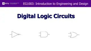
Introduction to Digital Electronic Circuits and Logic Gates
Understanding digital electronic circuits and logic gates is essential for building digital systems. This content covers the basics of logic gates, digital signals, and the practical application of binary digits in circuits. It discusses the function and importance of logic gates, such as NOT gates and buffer gates, in constructing digital circuits. Through illustrations and explanations, you will grasp the foundational principles of digital electronics and how logic gates are combined to design logic functions effectively.

Download Presentation

Please find below an Image/Link to download the presentation.
The content on the website is provided AS IS for your information and personal use only. It may not be sold, licensed, or shared on other websites without obtaining consent from the author. Download presentation by click this link. If you encounter any issues during the download, it is possible that the publisher has removed the file from their server.
E N D
Presentation Transcript
Digital Electronic 2ndsemester
Chapter Two Lecture 5 2
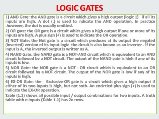
Logic Gates This chapter is devoted to practically apply the concept of binary digits to circuits. Logic gates are elementary bricks used in the construction of digital circuits. A logic gate is a special type of circuit designed to accept (inputs) and generate (outputs) voltages signals corresponding to binary digits (1 and 0). 3
Digital signals and gates: Let us consider the following circuit: When the switch is connected to the ground (0V), the light emitting diode (LED) does not shine. If we were using this circuit to represent binary digits, that means the input signal is a binary 0 and the output is a binary 0 or that the output is at the low logic level. Moving the switch to the other position (Vcc), Means a binary 1 is the input and receive a binary 1 at the output. The output is also said to be at the high logic level. 5
Digital signals and gates: This gate shown by this simple circuit is a buffer or yes gate, because the logic state of its input is identical to that of its output. Many types of gates are used in digital electronics: single input gates like the buffer and the NOT gates; multiple inputs gates like AND, NAND, OR, NOR and XOR gates. The aim of this chapter is to study the functioning of each of those logic gates and also how they can be combined to design a simple logic function. 6
2.3 The NOT gate: The NOT gate or Inverter is a logic gate which functions in such a way that the logic state of the output is exactly the opposite of that of the input. Remark 2.1: The truth table A truth table is a standard way of representing the Inputs/outputs relationships of a digital circuit, listing all the possible input logic level combinations with their respective output logic levels. The NOT gate truth table: 7
Remark 2.2: the buffer gate If two inverter gates were connected together, the output of one fed into the input of another. The two inversion functions would cancel each other out so that there would be no inversion from input to final output. A buffer is a special logic gate manufactured to perform the same function as two inverters connected together. Buffer gates serve to amplify signals, taking a weak signal source that is not capable of providing much current, and boosting the current capacity of the signal so as to be able to drive a load. 9
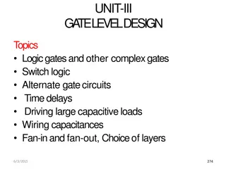
2.4 Multiple input gates: With a single input gate such as the inverter or buffer, there can only be two possible input states: either 1 or 0. With multiple input gates, many possibilities are available for input states. The number of possible input states is equal to two to the power of the number of inputs. So, if a gate has n inputs, therefore there are possible input combinations. 11
2.4.1 The AND gate: The output of the AND gate is high if and only if all inputs are high. If any input is low, the output is guaranteed to be in a low state as well. Truth table: Let us draw the truth table of a two inputs AND gate 12
2.4.1 The AND gate Truth table: Let us draw the truth table of a two inputs AND gate The output is high only when all the two inputs are high. 13
Exercises 14
Exercises 15
2.4.3 The OR gate: The output of the OR gate is high if any of the inputs is high. The output of an OR gate goes low if and only if all inputs are low. 16