Understanding Basic Logic Gates in Digital Electronics
Explore the fundamentals of digital electronics through the study of AND, OR, and NOT gates, their Boolean expressions, truth tables, and circuit realizations using diodes and transistors. Discover how NAND and NOR gates serve as universal gates, enabling complex logic operations. Dive into the principles of logic design with detailed explanations and visual representations.
Download Presentation

Please find below an Image/Link to download the presentation.
The content on the website is provided AS IS for your information and personal use only. It may not be sold, licensed, or shared on other websites without obtaining consent from the author. Download presentation by click this link. If you encounter any issues during the download, it is possible that the publisher has removed the file from their server.
E N D
Presentation Transcript
Digital Electronics 3 Dr. Apurba Kanti Deb Associate Professor AND, OR and NOT Gates (realization using Diodes and Transistor). NAND and NOR Gates as Universal Gates.
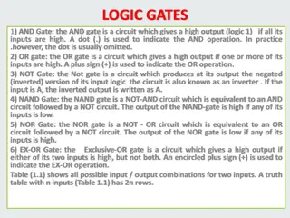
OR gate Two or more inputs, only one output. If any one or more inputs are in ON (1) state output is ON (1). If all the inputs are OFF (0) state only then output if OFF (0) Boolean expression Y= A+B+C+.. Truth table: for two inputs A B Y=A+B 0 0 0 0 1 1 1 0 1 1 1 1
OR gate A B C Y 0 0 0 0 0 0 1 1 Truth table: for three inputs 0 1 0 1 0 1 1 1 1 0 0 1 1 0 1 1 1 1 0 1 1 1 1 1 Circuit Symbol
OR gate Circuit realizing OR gate using diodes and Transistors
AND gate Two or more inputs, only one output. If any one or more inputs are in OFF (0) state output is OFF (0). If all the inputs are ON (1) state only then output if ON (1) Boolean expression Y= A.B.C.. Truth table: for two inputs A B Y=A.B 0 0 0 0 1 0 1 0 0 1 1 1
AND gate A B C Y 0 0 0 0 0 0 1 0 Truth table: for three inputs 0 1 0 0 0 1 1 0 1 0 0 0 1 0 1 0 1 1 0 0 1 1 1 1 Circuit Symbol
AND gate Circuit realizing AND gate using diodes and transistors
NOT gate Only one input, only one output. If inputs is in OFF (0) state output is ON (1) & If the input is in ON (1) state then output if OFF () Boolean expression Y= ? Truth table: A Y= ? 0 1 1 0 Circuit symbol:
NOT gate Circuit using Transistors
NAND gate Two or more inputs, only one output. If any one or more inputs are in OFF (0) state output is ON (1). If all the inputs are ON (1) state only then output if OFF (0) Boolean expression Y= ???.. Truth table: for two inputs Y=?? A B 0 0 1 0 1 1 1 0 1 1 1 0 from truth table Y= ?+ ? (bubbled or gate) De Morgan s theorem 2


