Introduction to Fluid Logic Control Systems
Fluid logic control systems utilize devices that switch fluid, like air, between outlets, providing ON/OFF outputs swiftly based on control signals. This article explores moving-part logic devices, control functions, Boolean algebra applications in control technology, and advantages of fluid logic systems, highlighting their suitability for varied applications.
Download Presentation

Please find below an Image/Link to download the presentation.
The content on the website is provided AS IS for your information and personal use only. It may not be sold, licensed, or shared on other websites without obtaining consent from the author. Download presentation by click this link. If you encounter any issues during the download, it is possible that the publisher has removed the file from their server.
E N D
Presentation Transcript
Fluid Logic Control Systems By: YOMNA RASHAD SUPERVISED By : Prof. KAMAL ABD-ELAZIZ Ass. Prof. ROLA AFIFY 1
Contents Introduction Advantages of Fluid Logic Control Systems Explain moving-part logic (MPL) devices. Discuss the control functions (OR/NOR, AND/NAND, NOT and EXCLUSIVE-OR). Perform the fundamental operations of Boolean algebra as related to control technology. Apply Boolean algebra techniques to control logic diagrams and control fluid power systems. 2
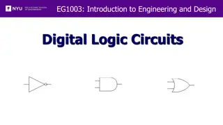
Introduction Fluid logic control systems use logic devices that switch a fluid, usually air, from one outlet of the device to another outlet. An output of a fluid logic device is either ON or OFF as it is rapidly switched from one state to the other by the application of a control signal. 3
Advantages of Fluid Logic Control Systems For example, fluid logic devices are not as adversely affected by temperature extremes, vibration, and mechanical shock. In addition, fluid logic systems are ideally suited for applications where electric arcing or sparks can cause a fire or an explosion. Fluid logic devices do not generate electric noise and therefore will not interfere with nearby electric equipment. 4
MPL ( Moving Part Logic ) Moving-part logic devices are miniature valve-type devices, which by the action of internal moving parts perform switching operations in fluid logic control circuits. MPL devices are typically available as spool, poppet, and diaphragm valves, which can be actuated by means of mechanical displacement, electric voltage, or fluid pressure. Moving-part logic circuits provide a variety of logic control functions for controlling the operation of fluid power systems. 5
An MPL pneumatic control package with a push button for ON/OFF operation. The subplate and the four valves mounted on it form a single push-button input providing a binary four-way valve output that is pressure and speed regulated by restrictions on the exhaust ports. 6
Boolean algebra serves two useful functions relative to controlling fluid power systems Boolean algebra is a two-valued algebra (0 or 1) that can be used to assist in the development of logic circuits for controlling fluid power systems. It provides a means by which a logic circuit can be reduced to its simplest form so that its operation can be more readily understood. It allows for a quick synthesis of a control circuit that is to perform desired logic operations. 7
MOVING-PART LOGIC (MPL) CONTROL SYSTEMS 8
AND Function The AND function can be represented for fluid flow systems by the case in which we have a number of MPL valves connected in series in a pipeline. The simplest case is for two valves with input signals A and B 9
OR Function An OR function can be represented in fluid flow systems by the case where an outlet pipe receives flow from two lines containing MPL valves controlled by input signals A and B. The OR function can be represented for fluid flow systems by the case in which we have a number of MPL valves connected in parallel in a pipeline. 10
NOT Function The NOT function is the process of logical inversion. This means that the output signal is NOT equal to the input signal. Since we have only two signal states (0 and 1), then an input of 1 gives an output of 0, and vice versa. 11
NAND Function NAND function is an inverted AND function 12
NOR Function NOR function is an inverted OR function 13
EXCLUSIVE-OR Function This is the case because an EXCLUSIVE-OR function gives an output only if input A or input B is ON 14
MEMORY Function MEMORY is the ability of a control system to retain information as to where a signal it has received originated. 15
Laws of Boolean Algebra There are a number of laws of Boolean algebra that can be used in the analysis and design of fluid logic systems. These laws are presented as follows: Commutative law: A + B = B + A A . B = B . A Associative law: A + B + C = ( A + B ) + C = A + ( B + C ) = ( A + C ) + B A . B . C = ( A . B ) . C = A . ( B . C ) = ( A . C ) . B Distributive law: A . ( B + C ) = ( A . B ) + ( A . C ) 16
Additional theorems that can be used to simplify complex equations and thus minimize the number of components required in a logic system are A + A = A A . A = A A + 1 = 1 A + 0 = A A . 1 = A A + ( A . B ) = A A . ( A + B ) = A ? = A A . ? = 0 A + ? = 1 17
MPL CONTROL OF FLUID POWER CIRCUITS 18
Control of Cylinder with Interlocks 1. The system provides interlocks and alternative control positions. 2. In order to extend the cylinder, either one of the two manual valves (A or B) must be actuated and valve C (controlled by a protective device such as a guard on a press) must also be actuated. 3. The output signal is memorized while the cylinder is extending. 4. At the end of the stroke, the signal in the MEMORY is canceled. 20
Boolean algebra is used to implement the use of programmable logic controllers (PLCs) 21
THANK YOU ANY QUESTIONS 22
