Understanding Computer Architecture and Digital Circuits
Computer architecture encompasses system design, instruction set architecture, and microarchitecture, defining how hardware and software interact to create a computer platform. Digital computers operate using the binary number system and logic gates to process information. Hardware description languages like Verilog and VHDL help in describing digital circuits efficiently.

Download Presentation

Please find below an Image/Link to download the presentation.
The content on the website is provided AS IS for your information and personal use only. It may not be sold, licensed, or shared on other websites without obtaining consent from the author. Download presentation by click this link. If you encounter any issues during the download, it is possible that the publisher has removed the file from their server.
E N D
Presentation Transcript
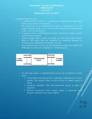
If people do not believe that mathematics is simple, it is only because they do not realize how complicated life is. .... John von Neumann Compute Architecture: o Computer Architecture is a specification describing how hardware and software technologies interact to create a computer platform or system. o Computer architecture consists of three main categories: System Design: This includes all the hardware data processors, multiprocessors, memory controllers and direct memory access. This part is the actual computer system. Instruction Set Architecture: This includes the CPU s functions and capabilities; the CPU s programming language, data formats, processor register types and programmers. This part is the software that makes it run, such as Windows or Photoshop etc. Microarchitecture: This defines the data processing and storage element or data paths and how they into the instruction set architecture. Digital Computers: o The digital computer is a digital system that performs various computational tasks. o Digital Computers use the binary number system, which has two digits: 0 and 1. A binary digit is called a bit. o Information is represented in digital computers in groups of bits. o By using various coding techniques, groups of bits can be made to represent not only binary numbers but also discrete symbols such as decimal digits or letters of the alphabet. Logic Gates: o Binary information is represented in digital computers by physical quantities called signals. Electric signals such as voltage exist throughout the computer in parts, such as CPU, instructions used by computer should be implemented
represent binary 1 while a signal of represent binary 0. The manipulation of binary information is done by logic circuits called gates. Gates are blocks of hardware that produce signals of binary 1 or 0 when input logic requirements are satisfied. The input-output relationship of the binary variables for each gate can be represented in tabular form by a truth table. The various logic gates are: AND OR NOT NAND NOR XOR XNOR Hardware Description Language(HDL): o HDL is a textual language that is specifically and concisely capture the defining features of digital design to describe the digital circuits. Another approach to describe a digital circuit is visual approach called schematic. In theory, we could interpret a CPU as a vast sea of transistors, but it is much easier to organize transistors into logic gates, logic gates into adders or registers or timing modules, registers into memory banks and so forth. This hierarchical structure allows us represent a digital circuit by means of interconnected diagrams. o The most popular hardware description languages are Verilog and VHDL (VHIC-HDL, Very High Speed Integrated Circuit Hardware Description Language). ABEL (Advanced Boolean obsolete. 0.5V may o o o intended to clearly to effectively Expression Language) now
The algebra operation symbol of the AND function is same as the multiplication symbol of ordinary arithmetic. We can either use a dot between the variables or concatenate the variables without an operation symbol representations of AND function is as below: between them. Other AND gates may have more than two inputs, and by definition, the output is 1 if and only if all inputs are 1.
The algebraic symbol of the OR function is +, similar to arithmetic addition. Other representations of OR function is as below: OR gates may have more than two inputs, and by definition, the output is 1 if any input is 1.
The algebraic symbol used for the logic complement is prime or a bar over the variable symbol. Other representations of NOT function are as below: either a NAND Gate: o The NAND function is the complement of the AND function, as indicated by the graphic symbol, which consists of an AND graphic symbol followed by a small circle.
The designation NAND is derived from the abbreviation of NOT- AND. NOR Gate: o The NOR gate is the complement of the OR gate and uses an OR graphic symbol followed by a small circle.
Exclusive- OR (XOR) Gate: o The output of XOR gate is 1 if any input is 1 but excludes the combination when both inputs are 1. XOR function can also be written as Z= X`Y+XY`. Other representations are as follows:
The exclusive-NOR operation is also termed as an odd function because its output is 1 if an odd number of inputs are 1. Other representations of XNOR are: