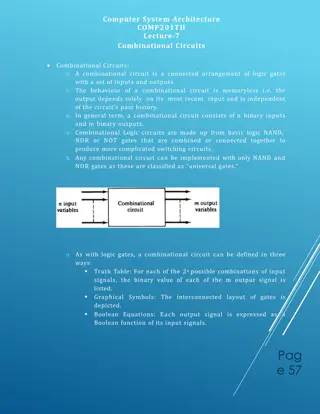
Introduction to Logic Gates and Truth Tables

Logic gates are fundamental building blocks of digital circuits. They include AND, OR, NOT, NAND, NOR, EX-OR, and XNOR gates, each with unique operations and truth tables. These gates manipulate binary signals to perform logical operations. The provided content explores the functions, symbols, and truth tables of these gates, emphasizing their uses and behaviors.

Download Presentation

Please find below an Image/Link to download the presentation.
The content on the website is provided AS IS for your information and personal use only. It may not be sold, licensed, or shared on other websites without obtaining consent from the author. Download presentation by click this link. If you encounter any issues during the download, it is possible that the publisher has removed the file from their server.
E N D
Presentation Transcript
LOGIC GATES 1) AND Gate: the AND gate is a circuit which gives a high output (logic 1) if all its inputs are high. A dot (.) is used to indicate the AND operation. In practice .however, the dot is usually omitted. 2) OR gate: the OR gate is a circuit which gives a high output if one or more of its inputs are high. A plus sign (+) is used to indicate the OR operation. 3) NOT Gate: the Not gate is a circuit which produces at its output the negated (inverted) version of its input logic the circuit is also known as an inverter . If the input is A, the inverted output is written as A. 4) NAND Gate: the NAND gate is a NOT-AND circuit which is equivalent to an AND circuit followed by a NOT circuit. The output of the NAND-gate is high if any of its inputs is low. 5) NOR Gate: the NOR gate is a NOT - OR circuit which is equivalent to an OR circuit followed by a NOT circuit. The output of the NOR gate is low if any of its inputs is high. 6) EX-OR Gate: the Exclusive-OR gate is a circuit which gives a high output if either of its two inputs is high, but not both. An encircled plus sign (+) is used to indicate the EX-OR operation. Table (1.1) shows all possible input / output combinations for two inputs. A truth table with n inputs (Table 1.1) has 2n rows.
Trough table Inputs Output A B AND OR NAND NOR EX-OR 0 0 0 0 1 1 0 0 1 0 1 1 0 1 1 0 0 1 1 0 1 1 1 1 1 0 0 0
symbols for the above-mentioned logic gates having two inputs 1. NOT-Gate Truth Table Input Output Z A 0 1 1 0 2. AND-Gate Truth Table Input Output A B Z 0 0 0 1 0 0 1 1 0 1 0 1
3. OR-Gate Truth Table Input Output Z A B 0 0 1 1 0 1 0 1 0 1 1 1 4. NAND-Gate Truth Table Input Output B A Z 0 0 1 1 0 1 0 1 1 1 1 0
5. NOR-Gate Truth Table Input Output Z B A 0 0 1 1 0 1 0 1 1 0 0 0 6. XOR-Gate Truth Table Input Output B A Z 0 0 1 1 0 1 0 1 0 1 1 0
7. XNOR-Gate Truth Table Input Output B A Z 0 0 1 1 0 1 0 1 1 0 0 1