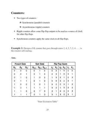
Understanding Digital Electronics Fundamentals with Prof. Dr. Ehssan Al-Bermany

Explore the basics of digital electronics with lectures on NOR gates, exclusive-OR gates, negative AND gates, and more. Understand how these circuits are equivalent to NOR and NAND gates. Discover key theorems of Boolean algebra through De Morgan's theorems. Prepare for a deep dive into Boolean algebra in the next chapter.

Download Presentation

Please find below an Image/Link to download the presentation.
The content on the website is provided AS IS for your information and personal use only. It may not be sold, licensed, or shared on other websites without obtaining consent from the author. Download presentation by click this link. If you encounter any issues during the download, it is possible that the publisher has removed the file from their server.
E N D
Presentation Transcript
Digital Electronic Prof. Dr. Ehssan Al-Bermany 2ndsemester
2.4.4 The NOR gate: The NOR gate is an OR gate with its output inverted. Truth table: Symbol: The NOR gate can also be manufactured with more than two inputs. 3
2.4.5 The exclusive-OR gate: The exclusive-OR gate outputs a high level only If the inputs are at different logic levels, either 0 and 1 or 1 and 0. Conversely, its output is low If the inputs are at the same logic levels. The exclusive-OR gate is sometimes called XOR gate. Truth table: 4
Remark 2.3: The negative AND gate and the negative OR gate. Let us consider the following digital circuit: a. Draw the truth table of this circuit. b. Show that this circuit is equivalent to a NOR gate. 5
Digital signals and gates: The expression of the output X can be written as follow: Therefore, the truth table of the circuit can be easily deduced: We can notice that the truth table of this circuit is identical to that of a NOR gate. The gate described in this exercise is called the negative AND gate and its symbol is given as follow: 6
Let us consider the following gate circuit: Draw the truth table of the circuit. Show that the circuit is equivalent to a NAND gate. The expression of the output X can be written as follow: Therefore, the truth table of the circuit can be easily deduced: 7
We can notice that the truth table of this circuit is identical to that of a NAND gate. The circuit described in this exercise is called the negative OR gate. Its symbol is given as follow: 8
The previous remark leads us to two important theorems of the Boolean algebra (the Boolean algebra will be studied in detail in the next chapter). Those theorems are called De Morgan s theorems: Where A and B are two Boolean variables (A Boolean variable is that which can only take values 0 and 1). 9
Exercise 2.9: Let us consider the following digital circuit: a. Give the expression of the output X. b. Draw the truth table of the circuit. 10
Exercise 2.10: Let us consider following gate circuit: a. b. c. Remark 2.5: From the exercise above the following property can be deduced: Determine the expression of the output. Deduce the truth table. Conclude. 11
1.1 Introduction The Boolean algebra was created by the English mathematician George Boole (1815-1864). The Boolean algebra codifies rules of relationship between mathematical quantities to one of two possible values: true or false, 1 or 0. All arithmetic operations performed with Boolean quantities have but one of two possible outcomes: either 1 or 0. There are three basic Boolean arithmetic operations: 1. Boolean addition which is equivalent to the OR logic function, as well as parallel switch contacts. 2. Boolean multiplication, which is equivalent to the AND function as well as series switch contacts. 3. Boolean complementation which is equivalent to the NOT logic function. 12
3.2 Boolean Arithmetic: This section presents the basic relationship concerning the three basic Boolean arithmetic operations. 3.2.1 Boolean addition: Boolean addition is equivalent to the OR logic function. Therefore, following relationships: 0 + 0 = 0 0 + 1 = 1 1 + 0 = 1 1 + 1 = 1 13
Remark 3.1: There is a difference between Boolean addition and binary addition; for binary addition we have the following relationships. 0 + 0 = 0 0 + 1 = 1 1 + 0 = 1 1 + 1 = 10 (1 + 1 = 0 + report of 1). 15
3.2.2 Boolean Multiplication: Is equivalent to the AND logic function: 0 x 0 = 0 0 x 1 = 0 1 x 0 = 0 1 x 1 = 1 16
3.2.3 Boolean Complementation: Is equivalent to the NOT logic function. 3.3 Boolean algebraic identities: An identity is a statement that is true for all possible values of its variables. There are two groups of Boolean algebraic identities: additive identities and multiplicative identities. 17
3.3.1 Additive identities If A is a Boolean variable, then the following statements are always true. A + 0 = A A + 1 = 1 A + A = A A + /A = 1 18
3.3.2 Multiplicative identities: A being a Boolean variable, the following statements are always true. 0 x A = 0 1 x A = A A x A = A A x/A = 0 19
Remark 3.2: Double complementation Complementing a variable twice results in the original Boolean value. 3.4 Boolean algebraic properties: Let us consider three Boolean Variables A, B and C. The following properties are true. 20
3.4 Boolean algebraic properties: Let us consider three Boolean Variables A, B and C. The following properties are true. Commutative property: - Addition: - Multiplication: A + B = B + A A x B = B x A Associative property: - Addition: A + (B + C) = (A + B) + C - Multiplication: A(B.C) = (A.B)C Distributive property: A(B + C) = A.B + A.C 21
3.5 Boolean rules for simplification: There are several rules for Boolean algebra intended to be used in reducing complex Boolean expressions to their simplest forms. The simplification of the Boolean expressions of logic circuits brings have many advantages: - Higher operating speed (less delay time from input signal transition to output signal transition). - Less power consumption (few IC used). - Less cost. - Greater reliability. 22
3.5 Boolean rules for simplification: 3.5.1 Rule 1: A + AB = A A + AB = A (1 + B) = A (1) = A 23
3.5 Boolean rules for simplification: 3.5.3 Rule 3: 24
3.6 Circuit simplification example: Let us consider the following logic circuit. 25