Understanding Binary Logic Systems in Documentation
Binary logic systems play a crucial role in documentation for individuals with diverse backgrounds such as management, process designers, operations staff, maintenance technicians, and more. These systems, depicted in binary logic diagrams, provide a clear and concise representation for various professionals to comprehend and apply in their respective fields. The integration of binary logic with analog and on-off control further enhances the efficiency and effectiveness of control systems in diverse industrial applications. By combining analog and on-off control schemes and utilizing different types of documentation, including process control descriptions, instrument diagrams, and functional diagrams, a comprehensive understanding and implementation of binary logic systems can be achieved.
Download Presentation

Please find below an Image/Link to download the presentation.
The content on the website is provided AS IS for your information and personal use only. It may not be sold, licensed, or shared on other websites without obtaining consent from the author. Download presentation by click this link. If you encounter any issues during the download, it is possible that the publisher has removed the file from their server.
E N D
Presentation Transcript
06/06/2017 Binary LogicSystems Chapter 06 Binary Logic Systems EMEC125 Why Binary Logic Systems? Documents need to be understood by people with very different backgrounds. People who could need the documentation are: Management ProcessDesigners OperationsStaffs Maintenance Technicians Electrical and Control SystemProfessionals Logic DeviceProgrammers Supervisory Control and Data Acquisition (SCADA) System Configurators Binary Logic Diagrams ISA-5.2-1976 (R1992) Binary Logic Diagrams for Process Operations and Scientific Apparatus Makers Association (SAMA) PMC 22.1 Functional Diagramming of Instrument and Control Systems. Both address binary logic diagrams. Elements of these standard are now included inANSI/ISA-5.1 1
06/06/2017 Terms You Should Know Before Proceeding DiscreteControl On/off control. One of the two output values is equal to zero. (International Society ofAutomation, 2003, p. 150) A better definition would be: A signal that is either fully ON or fully OFF with no valuesin-between. Binary 1. A term applied to a signal or device that has only two discrete positions or states. When used in its simplest form, as in binary signal (as opposed to analog signal ), the term denotes an on-off or high-low state, that is, one that does not represent continuously varying quantities. [ANSI-ISA-5.1-1984 (R1992)]. (InternationalSociety of Automation, 2003, p. 49). Terms You Should Know Before Proceeding Analog 1. Having the form of continuously variable physical quantities, as in data. Contrast with digital. 2. The representation of numerical quantities by means of physical variables, such as translation, rotation, voltage or resistance. 3. A waveform is analog if it is continuous and varies over an arbitrary range. Contrastwith digital. (InternationalSociety of Automation, 2003, p. 21). Another way to define Analog is: A continually varying signal that can be fully ON, fully OFF or any level in between. (International Society of Automation, 2003,p.21). Terms You Should Know Before Proceeding ProcessVariable 1. Any variable property of a process. The term process variable is used in the relevant standard to apply to all variables other than instrument signals [ANSI/ISA-5.1-1984 (R1992)]. 2. In the treatment of material, any characteristic or measurable attribute whose value changes with changes in prevailing conditions. Common variables are flow, level, pressure and temperature. (International Society of Automation, 2003, p.392). Control Variable (Controlled Variable) 1. The variable that the control system attempts to keep at the set point value. The set point may be constant or variable. 2. The part of a process to be controlled (flow, level, temperature, pressure, etc.). (International Society of Automation,2003, p.109). 2
06/06/2017 Combining Analog and On-Off Control Combining analog and on/off control schemes can be defined by using: Process control descriptions Instrumentdiagrams Functional diagrams Electrical schematicdiagrams These documents can be used independently or together depending upon the phase of design, construction or operation. Process Control Descriptions The more complex the process, the more detail that is required in a Process Control Description. The following are areas to be included, but not limited to,in a ProcessDescription: ProcessDescription Title of thesystem Generaldescription Form ControlDescription More specific data on how the system willperform Loop-by-loopdescriptions Format The Binary Concept Multiple Input This two-state binary concept, applied to gates, can be the basis for making decisions in ladderlogic. The gate is a device that has one or more inputs and one output. The gate will perform a logical decision based on the status of its inputs and produce a result at its one output. 3
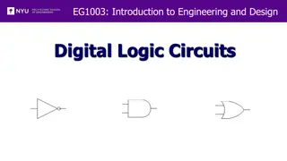
06/06/2017 Using Gates to Make Decisions The logical AND gate orfunction. Allinputs mustbe true to obtain an output. Air Conditioner Switch AND Cold Air Gate Blower Switch The automotive air conditioning to work, the Air Conditioner must be turned on and the Blower must be turned on. Using Gates to Make Decisions The logical OR gate orfunction. Any one input must be true to obtain anoutput. Passenger Door Switch OR Gate Dome Light Driver Door Switch The automotive dome light will be on when the passenger door OR the driver door or both door switch(s) isactivated. The ANDFunction The AND function has two or more inputs and one output. The input signals are labeled A, B, C, etc. and the output signal is labeledY. A binary 1 represents thepresence of a voltage (signal). A binary 0 represents the absence of voltage (no signal, 0 V orground). Logic functions can berepresented using a truth table. The truth table lists all possible input status conditions with the corresponding output status for each set of input condition. AND Gate Output A Y Inputs B Two input ANDgate 4
06/06/2017 An AND Gate Application An AND gate functions like switches inseries. The light will only be ON when switch A AND switch B are both closed. PB1=1 AND Gate LT1 ON PB2=1 The ORFunction The OR function has two or more inputs and one output. The input signals are labeled A, B, C, etc. and the output signal is labeledY. A binary 1 represents thepresence of a voltage (signal). A binary 0 represents the absence of voltage (no signal, 0 V orground). Logic functions can berepresented using a truth table. The truth table lists all possible input status conditions with the corresponding output status for each set of input condition. OR Gate A Output Y Inputs B Two input ORgate An OR Gate Application An OR gate functions like switches inparallel. The light will be ON when either or both switch A OR switch B are closed. PB3=1 OR LT2 ON PB4=0 Gate 5
06/06/2017 The NOT Function (Inverter) The NOT function gate, also called an inverter, has one input and oneoutput. The NOT gate functions like its name states, it inverts the input signalstatus. If the input is a 1 the output is a 0. If the input is a 0, the output is a 1. Input Input A A (not A) A NOT Gate Application The NOT gate functions like a normally closedswitch. The light will be ON if the switch is NOT being activated and OFF when the switch IS beingactivated. Input Input PB5 PB5 (notPB5) The NANDFunction NAND Gate PB6 Light The NAND gate functions like an AND gate with an INVERTER on itsoutput. The only time that the output of a NAND gate is a 0 is when all the inputs are a binary1. PB7 Two input NANDgate 6
06/06/2017 The NORFunction NOR Gate LT5 PB8 The NOR gate functions like an OR gate with an INVERTER on its output. The only time that the output of a NOR gate is a 1 is when all the inputs are a binary0. PB9 Two input NORgate The XOR (Exclusive- OR) Function XOR Gate PB10 LT6 The XOR gate has two inputs and one output. The output of this gate is a 1 when the two inputs are opposite to each other. Therefore, one input a 1 and the other a0. The output of this gate is a 0 when both inputs are the same, either two 0 s or two1 s. PB11 AND Gate Circuits Electromechanical Ladder Diagram PLC/PAC LadderDiagram AND Gate Output LS10 SOL010 Inputs LS10A Two input ANDgate 7
06/06/2017 OR Gate Circuits Electromechanical Ladder Diagram PLC/PAC LadderDiagram OR Gate Output LS011 Sol011 Inputs LS012 Two input ORgate Combinations of Gates Electromechanical Ladder Diagram PLC/PAC LadderDiagram OR LS013 AND Gate LT013 LS014 Gate Output Inputs CR Combination of Gates Electromechanical Ladder Diagram PLC/PAC LadderDiagram OR Gate LS015 LS016 AND Gate Inputs LT016 Output OR Gate CR01 CR02 8
06/06/2017 Combination of Gates Electromechanical Ladder Diagram PLC/PAC LadderDiagram AND Gate LS017 LS031 Output OR Gate Inputs AH017 LS018 Combination of Gates Electromechanical Ladder Diagram PLC/PAC LadderDiagram AND Gate PB019 PB020 Output OR Gate LT019 Inputs AND Gate PB021 PB022 Combination of Gates Electromechanical Ladder Diagram PLC/PAC LadderDiagram Why is this instruction programmedopen? CR6 AND Gate CR6 SOL021 Inputs Output LS021 9
06/06/2017 Combination of Gates Electromechanical Ladder Diagram Why are these instruction programmedopen? PLC/PAC LadderDiagram This is an XORcircuit Combination of Gates Electromechanical Ladder Diagram Draw thePLC/PAC ladder diagram for thislogic OR Gate A B Inputs AND Gate M CD Output Control Description (From ANSI/ISA-5.1) Control system designfor: Small volumes for long and short periods should allow tank to fill to a high level to automaticallystart the pump and then tostop the pump at a low level. Large volumes for long periods should allow the pump t run continuously and maintain a fixed level with a level-to-flow cascade control loop. Pump (run, or operation) control is selected by a three-position Hand-Off- Auto (H-O-A)selector switch: Selector switch is in HAND position. Selector switch is in AUTO position. Pump should be stopped at anytime: Automatically if low level isexceeded. By operation the stoppushbutton. Switching the H-O-A selector to OFF position. ISA 5.1(2009).pdf 10
06/06/2017 InstrumentDiagram STOP LSL LIC HS *02 *02 *02-B START LT HS HS LSH *02-A *01 *02 *02 T-1 FIC H-O-A *01 FT FV *01 *01 FO P-1 Functional Diagram Symbols Measuring, Input, or Readout Device [*] = Instrument Tag Number Symbols from Table 5.5 in the ANSI/ISA- 5.1-2009Standard (*) (*) Automatic single-modecontroller (*) Automatic two-mode controller (*) (*) (*) Automaticsinglecontroller (*) Manual signalprocessor (*) Final control element Control valve (*) Final control element with positioner Control valve withpositioner (*) Binary Logic AND & OR Gates A B C Y 0 0 0 0 AND 0 0 1 0 A B C A B C A N D 0 1 0 0 Y Y 0 1 1 0 1 0 0 0 1 0 1 0 1 1 0 0 1 1 1 1 A B C Y OR 0 0 0 0 0 0 1 1 A B C A B C 0 1 0 1 Y OR 0 1 1 1 1 0 0 1 1 0 1 1 1 1 0 1 1 1 1 1 11
06/06/2017 Binary Logic NOT & Memory NOT A A A A A A 0 1 NOT 1 0 A B C D 1 0 0 0 1 Memory 2 1 0 1 0 3 0 0 1 0 4 0 1 0 1 A C S 5 0 0 0 1 B D R 6 1 1 1 0 7 0 0 1 0 8 1 1 0 1 Electrical Schematic Ladder Diagram START HS*02-A M1 STOP H O A M HS*02-B LSL*02 OL M2 LSH*02 Logic Diagram Example Electrical STOP START COIL OVERLOAD RELAY CONTACTS Logic Pump Start A N D Pump Stop Pump Starts NOT Motor Starter, PumpMotor Overload S NOT R Motor Starter, Reset Pump Motor 12
06/06/2017 Function Block Diagram Allen Bradley (FYI) Function Block Diagram Siemens (FYI) Functional Diagram 1 when LSH*02 at High Level FT *01 LT *02 H A N D S A A Ro HS *01 H-O-A H OL T A N D START A N D P I P I PUMP P-1 OR HS A T A T A *02-A S 1 when NOT at Low Level LSL*02 Ro f (( * x) ) L A N D STOP NOT A N D HS FV*01 This diagram literally sucks SUQUE *02-B OL 13
06/06/2017 Functional Diagram 1 when at High Level M2 LSH*02 FT *01 LT *02 H A T P I P I A T A T A A LSL*02 HS *01 H-O-A Pump f((* x)) L H FV*01 OL 1 when NOT at STOP Low Level HS *02-B START HS *02-A M1 LabVolt Electrical Convert Ladder to Logic Gates 14
06/06/2017 Convert Ladder to Logic Gates Convert this Logic toLadder Summary This chapter discussed discrete control (on/off control) in a process plant. Logic diagrams will aid in the understanding of how Safety Instrumented Systems (SIS) work. Functional diagram symbols were discussed along with an example of how they areused. Basic logic gates have been discussed, along with the symbols used to representthem. 15
06/06/2017 References CEmark.com & European.Authorized-Representative.eu. (1996-2015). What is CE Marking (CE Mark)? Retrieved June 17, 2015, from Welkang Tech Consulting: http://www.ce-marking.org/what-is-ce- marking.html Charlet, T. (2016, September 8). How to Replace an Evaporator Temperature Sensor (Switch). Retrieved November 22, 2016, from Your Mechanic: https://www.yourmechanic.com/article/how-to-replace-an- evaporator-temperature-sensor-switch-by-timothy-charlet International Society of Automation. (2003). Automation, Systems, and Instrumentation Dictonary (4th ed.). Research Triangle Park: International Society of Automation. Retrieved from http://app.knovel.com/hotlink/toc/id:kpASIDE005/automation-systems-instrumentation/automation- systems-instrumentation International Society of Automation. (2009, September 18). ANSI/ISA-5.1-2009 Instrumentation Symbols and Identification. American National Standard. Research Triangle Park, North Carolina: International Society of Automation. Kirk, W. F., Weedon, A. T., & Kirk, P. (2014). Instrumentation and Process Control (6th ed.). Orland Park, Illinois: American Technical Publishers. References Lipt k, G. B. (Ed.). (1995). Process Measurement and Analysis (3rd ed.). Radnor, Pennsylvania: Chilton Book Company. McAvinew, T., & Mulley, R. (2004). Control System Documentation Applying Symbols and Identification (2nd ed.). Research Triangle Park, North Carolina, USA: International Society of Automation. Meier, F. A., & Meier, A. C. (2011). Instrumentation and Control Systems Documentation (2nd ed.). Research Triangle Park, North Carolina: International Society of Automation. Ruelas, E. (2016, January 6). Symptoms of a Bad or Failing AC Control Switch. Retrieved September 8, 2016, from Your Mechanic: https://www.yourmechanic.com/article/symptoms-of-a-bad-or-failing-ac-control- switch Shutterstock. (n.d.). Car Air Conditioner. Retrieved September 8, 2016, from Shutterstock: https://www.shutterstock.com/search/car+air+conditioner Sourceingmap. (n.d.). Car Vehicle Interior Door Courtesy Light Switch Button Part. Retrieved September 8, 2016, from Amazon.co.uk: https://www.amazon.co.uk/Vehicle-Interior-Courtesy-Switch-Button/dp/B00B0QLVSS References Wu, E. (2012, June 18). 2011 Chevy Camaro equipped with LED Interior Dome Lights. Retrieved September 8, 2016, from iJDMTOY Blog for Automotive Lighting: http://ijdmtoy.com/BLOG/wordpress/2012/06/18/2011-chevy- camaro-equipped-with-led-interior-dome- lights/ Thomas, E. C. (2015). Introduction to Process Technology (4th ed.). Boston, MA: Cengage Learning. 16


