Understanding Computer Architecture and Organization

Computer architecture and organization are fundamental aspects of computing systems. Computer architecture focuses on the functional design and implementation of various computer parts, while computer organization deals with how operational attributes come together to realize the architectural specification. The differences between architecture and organization lie in what the computer does versus how it does it, high-level versus low-level design issues, hardware versus performance emphasis, and more. The Central Processing Unit (CPU) serves as the core of a computer, executing instructions and managing data flow between components such as the Control Unit and Arithmetic Logic Unit.

Download Presentation

Please find below an Image/Link to download the presentation.
The content on the website is provided AS IS for your information and personal use only. It may not be sold, licensed, or shared on other websites without obtaining consent from the author. Download presentation by click this link. If you encounter any issues during the download, it is possible that the publisher has removed the file from their server.
E N D
Presentation Transcript
Computer architecture unit 1 Presented By: SANTOSH PRASAD GUPTA 7/19/2024 1
Content: Introduction CPU Computer Registers Instruction Execution Cycle Register transfer and micro operation Bus design Interrupts in microprocessor Memory reference instruction 7/19/2024 2
Introduction: Computer Architecture and Computer Organization Computer Architecture: Computer Architecture is a functional description of requirements and design implementation for the various parts of computer. It deals with functional behavior of computer system. It comes before the computer organization while designing a computer. Architecture describes what the computer does. Computer Organization: Computer Organization comes after the decide of Computer Architecture first. Computer Organization is how operational attribute are linked together and contribute to realise the architectural specification. Computer Organization deals with structural relationship. Organization describes how it does it. 7/19/2024 3
Differences between computer architecture and organization computer architecture Srno. Computer organization 1 Architecture describes what the computer does. Organization describes how it does it. 2 Computer Architecture deals with functional behavior of computer system. Computer Organization deals with structural relationship. 3 it deals with high-level design issue. it deals with low-level design issue. 4 Architecture indicates its hardware. Where, Organization indicates its performance. 5 Computer Architecture is also called as instruction set architecture. Computer Organization is frequently called as micro architecture. 6 Computer Architecture comprises logical functions such as instruction sets, registers, data types and addressing modes. Computer Organization consists of physical units like circuit designs, peripherals and adders. 7/19/2024 4
Central Processing Unit(CPU) The full form of CPU is Central Processing Unit. Alternatively, it is also known by the name of processor, microprocessor or a computer processor. A CPU is an electronics circuit used in a computer that fetches the input instructions or commands from the memory unit, performs arithmetic and logic operations and stores this processed data back to memory. A CPU or Central Processing Unit is the heart of a computer and is install in socket specified on a motherboard. Since a CPU performs a lot of calculations at a high speed, it gets heat up quickly. 7/19/2024 5
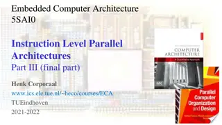
Components of a CPU 7/19/2024 6
Cont Control Unit The Control Unit is an internal part of a CPU that co-ordinates the instructions and data flow between CPU and other component of computer. It is the CU that directs the operations of a central processing unit by sending timing and control signals. Arithmetic Logic Unit The ALU is an internal electronic circuitry of a CPU that performs all the arithmetic and logical operations in a computer. The ALU receives three types of inputs. Control signal from CU ( Control Unit ) Data(operands) to be operated Status information from operations done previously. When all the instructions have been operated, the output that consists of data is stored in memory and a status information is stored in internal registers of a CPU. 7/19/2024 7
Cont.. Working of a CPU All the CPUs regardless of their origin or type performs a basic instruction cycle that consists of three steps named Fetch, decode and Execute. Fetch A program consists of a number of instructions. Various programs are stored in memory. During this step, the CPU reads instruction that is to be operated from a particular address in the memory. The program counter of CPU keeps the record of address of the instructions. Decode A circuitry called instruction decoder decodes all the instructions fetched from the memory. The instructions are decoded to various signals that control other areas of CPU. Execute In the last step, the CPU executes the instruction. For example, it stores a value in the particular register and the instruction pointer then points to other instruction that is stored in next address location. 7/19/2024 8
Computer Registers Registers are a type of computer memory used to quickly accept, store, and transfer data and instructions that a being used immediately by the CPU. The registers used by the CPU are often termed as Processor registers. A processor register may hold an instruction, a storage address, or any data (such as bit sequence or individual characters). The computer needs processor registers for manipulating data and a register for holding a memory address. The register holding the memory location is used to calculate the address of the next instruction after the execution of the current instruction is completed. Following is the list of some of the most common registers used in a basic computer: 7/19/2024 9
Cont Register Symbol Number of bits Function Holds memory operand Data register DR 16 Holds address for the memory Address register AR 12 Accumulator AC 16 Processor register Holds instruction code Instruction register IR 16 Holds address of the instruction Program counter PC 12 Holds temporary data Carries input character Carries output character Temporary register TR 16 Input register INPR 8 Output register OUTR 8 7/19/2024 10
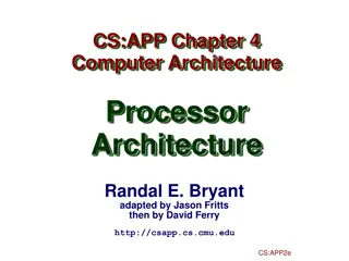
Cont The following image shows the register and memory configuration for a basic computer. 11 0 PC Memory 4096 word 16 bits per word 11 0 15 0 15 0 15 0 7 0 7 0 15 0 AR IR TR DR OUTR INPR AC 7/19/2024 11
Cont. The Memory unit has a capacity of 4096 words, and each word contains 16 bits. The Data Register (DR) contains 16 bits which hold the operand read from the memory location. The Memory Address Register (MAR) contains 12 bits which hold the address for the memory location. The Program Counter (PC) also contains 12 bits which hold the address of the next instruction to be read from memory after the current instruction is executed. The Accumulator (AC) register is a general purpose processing register. The instruction read from memory is placed in the Instruction register (IR). The Temporary Register (TR) is used for holding the temporary data during the processing. The Input Registers (IR) holds the input characters given by the user. The Output Registers (OR) holds the output after processing the input data. 7/19/2024 12
Instruction Execution Cycle All computers have an instruction execution cycle. A basic instruction execution cycle can be broken down into the following steps: Fetch cycle Execute cycle Although we have been concentrating on the CPU and memory, there are additional components in a computer such as the I/O modules which can interact with the processor. In an improved instruction execution cycle, we can introduce a third cycle known as the interrupt cycle. Figure 2 illustrates how the interrupt cycle fits into the overall cycle. 7/19/2024 13
Cont 7/19/2024 14
Fetch cycle To start off the fetch cycle, the address which is stored in the program counter (PC) is transferred to the memory address register (MAR). The CPU then transfers the instruction located at the address stored in the MAR to the memory buffer register (MBR) via the data lines connecting the CPU to memory. This transfer from memory to CPU is coordinated by the control unit (CU). To finish the cycle, the newly fetched instruction is transferred to the instruction register (IR) and unless told otherwise, the CU increments the PC to point to the next address location in memory. 7/19/2024 15
Cont. The illustrated fetch cycle above can be summarized by the following points: PC => MAR MAR => memory => MBR MBR => IR PC=PC+1 After the CPU has finished fetching an instruction, the CU checks the contents of the IR and determines which type of execution is to be carried out next. This process is known as the decoding phase. The instruction is now ready for the execution cycle. 7/19/2024 16
Execution cycle Once an instruction has been loaded into the instruction register (IR), and the control unit (CU) has examined and decoded the fetched instruction and determined the required course of action to take, the execution cycle can commence. Unlike the fetch cycle and the interrupt cycle, both of which have a set instruction sequence, the execute cycle can comprise some complex operations (commonly called opcodes). The actions within the execution cycle can be categorized into the following four groups: CPU - Memory: Data may be transferred from memory to the CPU or from the CPU to memory. CPU - I/O: Data may be transferred from an I/O module to the CPU or from the CPU to an I/O module. Data Processing: The CPU may perform some arithmetic or logic operation on data via the arithmetic-logic unit (ALU). Control: An instruction may specify that the sequence of operation may be altered. For example, the program counter (PC) may be updated with a new memory address to reflect that the next instruction fetched, should be read from this new location. For simplicity reasons, the following examples will deal with two operations that can occur. The [LOAD ACC, memory] and 7/19/2024 17
Conti [ADD ACC, memory], both of which could be classified as memory reference instructions. Instructions which can be executed without leaving the CPU are referred to as non-memory reference instructions. LOAD ACC, memory This operation loads the accumulator (ACC) with data that is stored in the memory location specified in the instruction. The operation starts off by transferring the address portion of the instruction from the IR to the memory address register (MAR). The CPU then transfers the instruction located at the address stored in the MAR to the memory buffer register (MBR) via the data lines connecting the CPU to memory. This transfer from memory to CPU is coordinated by the CU. To finish the cycle, the newly fetched data is transferred to the ACC. 1 The illustrated LOAD operation (Figure 4) can be summarized in the following points: 2 IR [address portion] => MAR 3 MAR => memory => MBR 4 MBR => ACC 7/19/2024 18
Cont.. 7/19/2024 19
ADD ACC, memory This operation adds the data stored in the ACC with data that is stored in the memory location specified in the instruction using the ALU. The operation starts off by transferring the address portion of the instruction from the IR to the MAR. The CPU then transfers the instruction located at the address stored in the MAR to the MBR via the data lines connecting the CPU to memory. This transfer from memory to CPU is coordinated by the CU. Next, the ALU adds the data stored in the ACC and the MBR. To finish the cycle, the result of the addition operation is stored in the ACC for future use. The illustrated ADD operation (Figure 5) can be summarised in the following points: 1 IR [address portion] => MAR 2 MAR => memory => MBR 3 MBR + ACC => ALU 4 ALU => ACC 7/19/2024 20
After the execution cycle completes, if an interrupt is not dedect, the next instruction is fetched and the process starts all over again. Interrupt Cycle An interrupt can be described as a mechanism in which an I/O module etc., can break the normal sequential control of the central processing unit (CPU). Table 1 below, summarizes the most common form of interrupts that the CPU can receive. The main advantage of using interrupts is that the processor can be engaged in executing other instructions while the I/O modules connected to the computer are engaged in other operations. 7/19/2024 21
Cont.. Program Generated by some condition that occurs as a results of an instruction execution, such as arithmetic overflow, division by zero, attempt to execute am illegal machine instruction, and reference outside a user's allowed memory space. Timer Generated by a timer within the processor. This allows the operating system to perform certain functions on a regular basis. Generated by an I/O controller, to signal normal completion of an operation or to signal a variety of error conditions. Generated by a failure such as power failure or memory parity error. I/O Hardware failure 7/19/2024 22
Cont.. Up until now we have dealt with the instruction execution cycle on the hardware level. When interrupts are introduced, the CPU and the operating system driving the system, is responsible for the suspension of the program currently being run, as well as restoring that program at the same point before the interrupt was detected. To handle this, an interrupt handler routine is executed. This interrupt handler is usually built into the operating system. Before the interrupt handler routine can ran, several processes must occur first. A typical sequence of events is illustrated in Figure 6 below. After the completion of the interrupt handler routine, the normal sequencial fetch / execute cycle begins. 7/19/2024 23
Cont.. 7/19/2024 24
Register transfer and micro operation In symbolic notation, it is used to describe the micro-operations transfer among registers. It is a kind of intermediate representation (IR) that is very close to assembly language, such as that which is used in a compiler. The term Register Transfer can perform micro-operations and transfer the result of operation to the same or other register. Micro-operations : The operation executed on the data store in registers are called micro-operations. They are detailed low-level instructions used in some designs to implement complex machine instructions. Register Transfer : The information transformed from one register to another register is represented in symbolic form by replacement operator is called Register Transfer. Replacement Operator : In the statement, R2 <- R1, <- acts as a replacement operator. This statement defines the transfer of content of register R1 into register R2. 7/19/2024 25
Cont.. There are various methods of RTL 1 General way of representing a register is by the name of the register inclosed in a rectangular box as shown in (a). 2 Register is numbered in a sequence of 0 to (n-1) as shown in (b). 3 The numbering of bits in a register can be marked on the top of the box as shown in (c). 4. A 16-bit register PC is divided into 2 parts- Bits (0 to 7) are assigned with lower byte of 16- bit address and bits (8 to 15) are assigned with higher bytes of 16-bit address as shown in (d) 7/19/2024 26
Cont.. 7/19/2024 27
Cont.. It indicates that if P=1, then the content of R1 is transferred to R2. It is a unidirectional operation. Simultaneous Operations If 2 or more operations are to occur simultaneously then they are separated with comma (,). If the control function P=1, then load the content of R1 into R2 and at the same clock load the content of R2 into R1. 7/19/2024 28
Bus design System Bus Design Bus is a communication channel. Characteristic of bus is shared transmission media. Limitation of a bus is only one transmission at a time. A bus which is used to provide the communication between the major components of a computer is called as System bus. 7/19/2024 29
Cont.. System bus contains 3 categories of lines used to provide the communication between the CPU, memory and IO named as: 1. Address lines (AL) Data lines (DL) 2 3. Control lines (CL) 1. Address Lines: Used to carry the address to memory ad IO. Unidirectional. Based on width of a address bus we can determine the capacity of a main memory Example: 7/19/2024 30
Cont.. 7/19/2024 31
2. Data Lines: Used to carry the binary data between the CPU, memory and IO. Bidirectional. Based on the width of a data bus we can determine the word length of a CPU. Based on the word length we can determine the performance of a CPU. Example: 7/19/2024 32
Cont.. 7/19/2024 33
3. Control Lines: Used to carry the control signals and timing signals Control signals indicates type of operation. Timing Signals used to synchronize the memory and IO operations with a CPU clock. 7/19/2024 34
Interrupts in microprocessor An interrupt is a condition that halts the microprocessor temporarily to work on a different task and then return to its previous task. Interrupt is an event or signal that request to attention of CPU. This halt allows peripheral devices to access the microprocessor. Whenever an interrupt occurs the processor completes the execution of the current instruction and starts the execution of an Interrupt Service Routine (ISR) or Interrupt Handler. ISR is a program that tells the processor what to do when the interrupt occurs. After the execution of ISR, control returns back to the main routine where it was interrupted. 7/19/2024 35
Cont In 8086 microprocessor following tasks are performed when microprocessor encounters an interrupt: The value of flag register is pushed into the stack. It means that first the value of SP (Stack Pointer) is decremented by 2 then the value of flag register is pushed to the memory address of stack segment. The value of starting memory address of CS (Code Segment) is pushed into the stack. The value of IP (Instruction Pointer) is pushed into the stack. IP is loaded from word location (Interrupt type) * 04. CS is loaded from the next word location. Interrupt and Trap flag are reset to 0. 7/19/2024 36
Cont The different types of interrupts present in 8086 microprocessor are given by: Hardware Interrupts Hardware interrupts are those interrupts which are caused by any peripheral device by sending a signal through a specified pin to the microprocessor. There are two hardware interrupts in 8086 microprocessor. They are: (A) NMI (Non Maskable Interrupt) It is a single pin non maskable hardware interrupt which cannot be disabled. It is the highest priority interrupt in 8086 microprocessor. After its execution, this interrupt generates a TYPE 2 interrupt. IP is loaded from word location 00008 H and CS is loaded from the word location 0000A H. (B) INTR (Interrupt Request) It provides a single interrupt request and is activated by I/O port. This interrupt can be masked or delayed. It is a level triggered interrupt. It can receive any interrupt type, so the value of IP and CS will change on the interrupt type received. 7/19/2024 37
Cont Software Interrupts These are instructions that are inserted within the program to generate interrupts. There are 256 software interrupts in 8086 microprocessor. The instructions are of the format INT type where type ranges from 00 to FF. The starting address ranges from 00000 H to 003FF H. These are 2 byte instructions. IP is loaded from type * 04 H and CS is loaded from the next address give by (type * 04) + 02 H. Some important software interrupts are: (A) TYPE 0 corresponds to division by zero(0). (B) TYPE 1 is used for single step execution for debugging of program. (C) TYPE 2 represents NMI and is used in power failure conditions. (D) TYPE 3 represents a break-point interrupt. (E) TYPE 4 is the overflow interrupt. 7/19/2024 38
Memory reference instruction The basic computer has 16-bit instruction register (IR) which can denote either memory reference or register reference or input-output instruction. Memory Reference These instructions refer to memory address as an operand. The other operand is always accumulator. Specifies 12-bit address, 3-bit opcode (other than 111) and 1-bit addressing mode for direct and indirect addressing. Example IR register contains = 0001XXXXXXXXXXXX, i.e. ADD after fetching and decoding of instruction we find out that it is a memory reference instruction for ADD operation. Hence, DR M[AR] AC AC + DR, SC 0 7/19/2024 39
7/19/2024 40


")


![❤Book⚡[PDF]✔ The Apollo Guidance Computer: Architecture and Operation (Springer](/thumb/21611/book-pdf-the-apollo-guidance-computer-architecture-and-operation-springer.jpg)