Understanding the 8051 Microcontroller: Features, Registers, and Applications
A detailed overview of the 8051 microcontroller including its introduction, features, and registers. Explore how the 8051 is useful for small computing tasks, control applications, and its low power consumption. Learn about the various registers in the 8051 such as the accumulator, program counter, timer registers, and more. Discover the applications and relevance of the 8051 microcontroller in modern technology.

Download Presentation

Please find below an Image/Link to download the presentation.
The content on the website is provided AS IS for your information and personal use only. It may not be sold, licensed, or shared on other websites without obtaining consent from the author. Download presentation by click this link. If you encounter any issues during the download, it is possible that the publisher has removed the file from their server.
E N D
Presentation Transcript
IDHAYA COLLEGE FOR WOMEN KUMBAKONAM 612 001 DEPARTMENT OF PHYSICS SEMESTER CLASS : : II II M.Sc., PHYSICS SUBJECT- INCHARGE : Ms. A. BHARATHI SUBJECT NAME : MICROPROCESSOR AND MICROCONTROLLER P16PYE1 SUBJECT CODE TOPIC : : 8051 MICROCOTROLLER
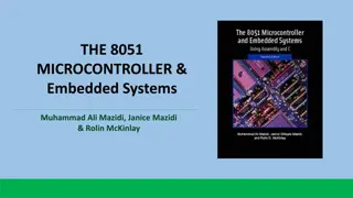
MICROCONTROLLER MICROCONTROLLER 8051 8051
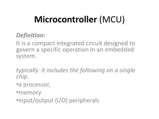
INTRODUCTION A single chip computer or a CPU with all the peripherals like RAM,ROM,I/O, Timers, ADCs, etc on the same chips. A Microcontroller is meant to be more self- contained and independent, and functions ads a tiny, dedicated computer. Originally, 8051 Microcontrollers were developed using N-MOS Technology but the use of battery powered devices and their low power consumption lead to usage of CMOS Technology (which is famous for its low power consumption). Majority of the modern 8051 Microcontrollers are Silicon IP Cores (Intellectual Property Cores) but discrete 8051 Microcontroller IC s are also available. Because of their low power consumption, smaller size and simple architecture, 8051 IP Cores are used in FPGAs (Field Programmable Gate Array) and SoCs (System on Chip) instead of Advanced ARM Architecture based MCUs.
FEATURES OF 8051 Useful for small computing tasks. Adequate for many control and monitoring application. Packaging (RAM, ROM, Timers on chip). Less power consumption. Easily upgradable. Availability of tools of microcontroller such as proteus (simulator) and keil (compiler).
REGISTERS: OF 8051 The 8051 is an accumulator based microcontroller. Its registers are: register A, PSW, register B, 8-bit stack pointer, 16-bit data pointer, program counter, program address register, 16-bit timer registers for timer/counters, instruction register, control registers, RAM address register, serial data buffer, capture registers, special function registers etc., Register B is used during multiply and divide operations. Data pointer: It consists of DPH( a high byte) and DPL(a low byte). It holds 16- bit address. It can be used as a 16-bit register or a two independent 8- bit registers. Serial Data Buffer: It consists of two separate registers, a transmit buffer register and a receive buffer register. Timer Registers: (TL0,TH0), (TL1,TH1), and (TL2,TH2) are register pairs. These register pain are 16-bit counting registers for Timer/counter 0,1, and 2 respectively.
Program Counter: The Intel 8051 microcontroller contains a 16-bit program counter (PC) register. It points to the address of the next instruction of the program which is to be fetched and executed. It is automatically incremented after fetching an instruction. It keeps the track of memory addresses of the instructions in the program being executed. It is affected by JUMP and CALL instructions. Stack pointer (SP): Intel 8051 microcontroller contains an 8-bit stack pointer register. It is incremented before data is stored during PUSH and CALL operations. It is decremented when POP or RET (Return) operation takes place. Any area of on-chip RAM can be used.
PSW (Program Status Word): PSW register contains program status information. Its bits are indicated by PSW.0, PSW.1, PSW.2, .., PSW.7 7 6 5 4 3 2 1 0 CY AC F0 RS1 RSO Bit No OV - P Status information Bit No. 0, PSW.0. It is for parity status (Parity flag, P). Bit No. 1, PSW.1. Reserved. Bit No. 2, PSW.2. Overflow flag (OV). Bit No. 3, PSW.3. (RS0) Bit No. 4, PSW.4. (RS1) Bit No. 5, PSW.5. It is Flag 0(F0) available to users for general purpose. Bit No. 6, PSW.6. It is auxiliary carry flag (AC). Bit No. 7, PSW.7. It is carry flag (CY). These bits are to select working register bank.


: PSW register contains program")
: PSW register contains program")
: PSW register contains program")
: PSW register contains program")
: PSW register contains program")
: PSW register contains program")
: PSW register contains program")