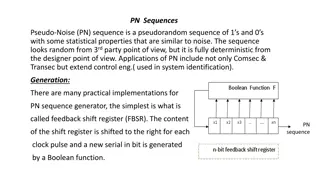
Understanding Shift Registers in Digital Electronics

Shift registers are a fundamental concept in digital electronics where binary numbers are shifted from one flip-flop to the next. They come in various types like SISO, SIPO, PISO, and PIPO, serving different purposes such as delay lines, data converters, sequential memory, and ring counters. The operational modes and applications of shift registers are crucial in understanding digital circuit design.

Uploaded on Jul 20, 2024 | 0 Views
Download Presentation

Please find below an Image/Link to download the presentation.
The content on the website is provided AS IS for your information and personal use only. It may not be sold, licensed, or shared on other websites without obtaining consent from the author. Download presentation by click this link. If you encounter any issues during the download, it is possible that the publisher has removed the file from their server.
E N D
Presentation Transcript
SHIFT REGISTERS By Asst. Lect. Radhi S. Issa 2018-2019 15
SHIFT REGISTERS A shift register is a group of FFs arranged so that the binary numbers stored in the FFs are shifted from one FF to the next, for every clockpulse. The waveforms of J-K flip-flops operated as a four-bit shift register: 16
Basic Shift Register Types (Classifications of operation modes): 1. Serial in/serial out shift registers (SISO) 10110 10110 2. Serial in Parallel out shift register (SIPO) 10110 10110 3. Parallel in serial out registers (PISO) 10110 10110 4. Parallel in parallel out shift registers (PIPO) 10110 10110 5. Bidirectional shift registers (shifts left and right) 17
6. Universal ( a single device that is all of the above) , such as the TTL 74LS194, 74LS195 or the CMOS 4035 which are available as 4-bit multi-function devices. -------------------------------------------------------------------------------------------------- 1. SISO Flip-Flop Shift Register The data is shifted serially IN and OUT of the register, one bit at a time in either a left or right direction under clock control. 2. SIPO Flip-Flop Shift Register The register is loaded with serial data, one bit at a time, with the stored data being available at the output in parallel form. 3. PISO Flip-Flop Shift Register The parallel data is loaded into the register simultaneously and is shifted out of the register serially one bit at a time under clock control.
18 4. PIPO Flip-Flop Shift Register The parallel data is loaded simultaneously into the register, and transferred together to their respective outputs by the same clock pulse.
19 Application of Shift Registers: 1) Delay Line The serial in serial out shift register can be used as a time delay device. The amount of delay can be controlledby: A. The number of stages in the shift register. B. The clock frequency. t = (n-1)T n: number of stages, t: time delay T=1 Fc 2) serial to parallel converter Data in the serial form can be converted into parallel form by using a SIPO shift register. 3) Parallel-to-Serial Converter: Data in the parallel form can be converted into serial form by using a PISO shift register. 4) Sequential memory: The shift register can be used as a memory storage unit. The ring counter can be arranged to do the storage operation by continuously feeding the data back, and first by parallel loadingit. 5) Ring Counter: when entering 0001in the parallel form of a 4 bit ring counter after clearing the flip flops, and the clock pulses are applied, the ring counter takes the serial output of the last Flip-Flop of a shift register and provides it to the serial input of the first Flip-Flop. Ring Counters are also known as re-circulating shift registers 20
Rotational Movement of a 4 bit Ring Counter: "SignalWaveform" 21
Example: Design a 6-bit (MOD-6) ring counter "SequenceTable" "StateDiagram" 22
6) Twisted-Ring Counter (Johnson Counters): The complement of the output of the last stage is connected back to the input of the first stage. These counters require fewer flip-flops than ring counters but more flip- flops than binary counters. An n-bit Johnson counter cycles through 2n states. Require more decoding circuitry than ring counters but less than binary counters. Example : Implement the complete design for a 4-bit (MOD-8) Johnson counter. 23
"Sequencetable" "StateDiagram" 24


 ,")


 ring counter")
 Twisted-Ring Counter (Johnson Counters):")