Understanding Addressing Modes in 8051 Microcontroller
Addressing modes in the 8051 microcontroller play a crucial role in specifying how data is accessed and operated by instructions. They include register addressing, direct addressing, register indirect addressing, immediate addressing, and indexed addressing modes. Each mode offers unique ways to handle data efficiently, enhancing CPU processing speed and reducing processing time. With specific examples and explanations, this guide delves into the diverse addressing modes of the 8051 MC.
Download Presentation

Please find below an Image/Link to download the presentation.
The content on the website is provided AS IS for your information and personal use only. It may not be sold, licensed, or shared on other websites without obtaining consent from the author. Download presentation by click this link. If you encounter any issues during the download, it is possible that the publisher has removed the file from their server.
E N D
Presentation Transcript
Addressing Modes Addressing Modes in in 8051 MC 8051 MC S. Lourduraj Asst. Prof. of Physics St. Joseph s College.
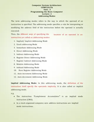
Addressing Mode MC 8051 Method of specifying the data to be operated by the instruction CPU can access the data in various ways. -- data could be in reg./Memory/immediate value. Is a way the MC to access data / operand from internal memory /external memory (or)Register specific Ports. The use of efficient modes of a program (addressing mode) will increase the processing speed of CPU as well as processing time can be shortened.
Types of Addressing Modes 1.Register Addressing Mode 2.Direct Addressing Mode 3.Register indirect Addressing Mode 4.Immediate Addressing Mode 5.Indexed Addressing mode
1. Register Addressing mode - Instruction will specify the name of the Reg. in which data is available This addressing instruction involves information transfer between registers (at least one of the R0-R7 register involved) i) Source & Destination reg. s match in Size: MOV A, R0 MOV R2, A ADD A, R5 Eg: Eg: MOV R4, R5 (Invalid Instruction) ii) Size of Source & Destination will vary: Eg: MOV DPTR, A (Error) MOV DPTR, #12A3H MOV R2, DPL MOV R1, DPH
1. Register Addressing mode Example: ADD A, R7 ; add content of A with the content of R7 MOV R0,#00 ; move data 00 to the register R0 DJNZ R3, LOOP ; Decrement content of R3 and Jump if Not LOOP MOV R0, A ; The instruction transfers the content of accumulator A into the R0 register.
2. Direct Addressing mode The Address of the data is directly specified in the instruction The entire 128 bytes of RAM can be accessed with memory locations 30H to 7FH Eg: MOV R2, #5 R2=05H MOV B, 2 MOV R0, 40H MOV R4, 7FH MOV 40H, A MOV A, 7 OR MOV A, R7 (OR) MOV A, 7 MOV 4, 2 (OR) MOV R4, R2 Eg: MOV A, P3 MOV A, 020H MOV P1, AA H ; Transfer the contents of A to Port 1 MOV 20H, 40H ; Transfer the contents of the address 40H to the address 20H ADD A, 55H ; Add the contents of A with the contents of the address 55H ; Transfer the contents of Port 3 to the accumulator ; Transfer the contents of RAM location 20H to the accumulator
Addressable memory used by direct addressing mode from 00 to 7F and also address specified by special register Valid memory Address for Direct Addressing Mode P1(80H), P1(90H), P2(A0H), P3(B0H) & PSW(D0H) PSW(D0H)
3. Register Indirect Addressing mode A register is used to hold the effective address of the operand. This register, which holds the address, is called the Pointer register and is said to point to the operand. Only registers R0, R1 and DPTR can be used as pointer registers. R0 and R1 registers can hold an 8-bit address where as DPTR can hold a 16-bit address. DPTR is useful in accessing operands which are in the external memory.
3. Indirect Addressing mode (contd) Examples: MOV @ R0, A ;Store the content of accumulator into the memory location pointed to by the contents of register R0. R0 could have an 8-bit address, such as 60H. Eg: MOV P1, #0xFF H MOV A, P1 MOV R0, # 050H MOV @R0, A MOV A, @R0 Let P1: 0000 0100b (OR) 04 H A = 04H R0 = 50 H Add. of Memory 0050 H = ------ A = ---H MOV A, @R0 ; move the contents of RAM at location designated by R0 into accumulator A
MOVX A, @ DPTR ; Transfer the contents from the memory location pointed to by DPTR into the accumulator. DPTR could have a 16-bit address, such as 1234 H. INC @R1 add one into the content designated by the R1
Example MOV A, #55H MOV R0, 40H MOV @R0, A INC R0 A= 55h R0 40H= ( xx ) 40H = --- H R0 = 41 H MOV @R0, A INC R0 41 H = ---H R0 = 42H MOV @R0,A INC R0 MOV @R0, A 42H = ----H R0 = 43H 43 H= ----H Advantages of reg. Indirect addressing Mode: Limitations: need to access the external RAM Looping is most efficient & Block data transfer
4. Immediate Addressing mode This mode of addressing uses either an 8- or 16-bit constant value as t he source operand This constant is specified in the instruction, rather than in a register or a memory location The destination register should hold the same data size which is specified by the source operand Examples: ADD A, # 030H ;Add 8-bit value of 30H to the accumulator register (which is an 8-bit register). MOV DPTR, #0FE00 H ;Move 16-bit data constant FE00H into the 16-bit Data Pointer Register.
4. Immediate Addressing mode (contd) Examples: MOV A, # A0H ADD A, # 4EH CJNE A, # 20H, LOOP ; compare the data 20H with content of Acc (A), ; data A0H transfer to the A ; add the contents of A with the data 4E H & store in Acc. A jump to LOOP if the value not equal to zero.
5. Indexed Addressing mode On-Chip ROM access The Indexed addressing is useful when there is a need to retrieve data from a look-up table A 16-bit register (data pointer/program counter DPTR/PC) holds the base address and the accumulator holds an 8-bit displacement or index value The sum of these two registers forms the effective address for a JMP or MOVC instruction
Indexed Addressing mode (contd) Example: MOV A, #08H ; Offset from table start MOV DPTR, #01F00H ; Table start address MOVC A, @ A+DPTR ; Gets target value from the table start address + offset and puts it in A. (Contents of A are added to the 16 bit reg. DPTR to form the 16 bit address of need data ) After the execution of the above instructions, the program will branch to address 1F08H (1F00H+08H) and transfer into the accumulator the data byte retrieved from that location (from the look-up table) (A) { (A=00) + (Add. Of content) }
ORG 0000 MOV DPTR, #200H CLR A MOVC A, @A+DPTR MOV R0,A HERE: ORG 0200H MY DATA: DB SLR END. INC DPTR CLR A MOVC A,@A+DPTR MOV R1, A INCR DPTR CLR A MOVC A,@A+DPTR MOV R2, A SJMP HERE
Program to understand the concept of LOOK UP table with INDEXED ADDRESSING MODE ORG 0000 MOV DPTR, #300H MOV A, #0FFH MOV P1, A BACK: MEMORY LOCATIONS IN ROM 307CONTENTS 300 00 301 01 MOV A, P1 MOVC A, @A+DPTR MOV P2 ,A SJMP BACK 302 04 303 09 304 10 Equivalent to 16 305 19 Equivalent to 25 306 24 Equivalent to 36 SQR_Table: DB 0, 1, 4, 9, 16, 25, 36, 49, 64, 81 END. ORG 300H 307 31 Equivalent to 49 308 40 Equivalent to 64 309 51 Equivalent to 81


