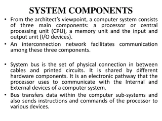
Understanding Computer Architecture: CPU Structure and Function

Delve into the intricate world of computer architecture with Prof. Dr. Nizamettin AYDIN as your guide. Explore topics such as CPU structure, registers, instruction cycles, data flow, pipelining, and handling conditional branches. Gain insights into the responsibilities of a CPU, internal structures, memory hierarchy, and the significance of various registers. Discover the program status word and its role in conveying crucial status information. Uncover the foundations of system buses, address registers, and control units in ensuring the seamless operation of modern processors.

Download Presentation

Please find below an Image/Link to download the presentation.
The content on the website is provided AS IS for your information and personal use only. It may not be sold, licensed, or shared on other websites without obtaining consent from the author. Download presentation by click this link. If you encounter any issues during the download, it is possible that the publisher has removed the file from their server.
E N D
Presentation Transcript
Computer Architecture Prof. Dr. Nizamettin AYDIN naydin@yildiz.edu.tr nizamettinaydin@gmail.com http://www.yildiz.edu.tr/~naydin 1
Computer Architecture CPU Structure and Function 2
Outline CPU Structure Registers Instruction Cycle Data Flow Instruction Pipelining Dealing with conditional Branches 3
CPU Structure A CPU is responsible for... fetching instructions interpreting instructions fetching data processing data writing data CPU With Systems Bus CPU Internal Structure 4
Registers Top level of memory hierarchy Temporary storage User-visible registers Enable the machine- or assembly language programmer to minimize main memory references by optimizing use of registers Control and status registers Used by the control unit to control the operation of the processor and by priviliged, operating system programs to control the execution of programs 5
Registers User Visible Registers General Purpose registers Data registers Address registers Condition Codes (flags) Control & Status Registers Program Counter (PC) Contains the address of an instruction to be fetched Instruction Decoding Register (IR) Contains the instruction most recently fetched Memory Address Register (MAR) Contains the addres of location in memory Memory Buffer Register (MBR) Contains a word or data to be written to memory or the word most recently read 6
Program Status Word A set of bits containing status information Includes Condition Codes (flags) Sign sign of last result Zero set when the result is 0 Carry set if an operation resulted in a carry (addition) into or borrow (subtraction) out of a high order bit Equal set if a logical compare result is equality Overflow used to indicate arithmetic overflow Interrupt enable/disable used to enable or disable interrupts Supervisor Indicates whether the processor is executing in superviser mode or user mode. Certain privileged instructions can be executed only in supervisor mode, and certain areas of memory can be accessed only in supervisor mode 7
Instruction Cycle Instruction Cycle Fetch Execute Interrupt Indirect Cycle May require memory access to fetch operands Indirect addressing requires more memory accesses Can be thought of as additional instruction subcycle 9
Data Flow (Instruction Fetch) Depends on CPU design In general following events take place in an instruction cycle: Fetch PC contains address of next instruction Address moved to MAR Address placed on address bus Control unit requests memory read Result placed on data bus, copied to MBR, then to IR Meanwhile PC incremented by 1 11
Data Flow (Data Fetch) IR is examined If indirect addressing, indirect cycle is performed Right most N bits of MBR transferred to MAR Control unit requests memory read Result (address of operand) moved to MBR 12
Data Flow (Execute) May take many forms Depends on instruction being executed May include Memory read/write Input/Output Register transfers ALU operations 13
Data Flow (Interrupt) Current PC saved to allow resumption after interrupt Contents of PC copied to MBR Special memory location (e.g. stack pointer) loaded to MAR MBR written to memory PC loaded with address of interrupt handling routine Next instruction (first of interrupt handler) can be fetched 14
Some strategies to increase the computer performance Faster circuitry Multiple registers Cache memory Parallel processing Pipelining Etc... .... 15
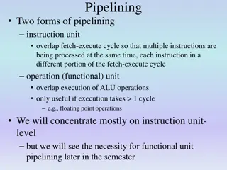
Instruction Pipelining- Similar to assembly line in a manifacturing plant Remember that an instruction cycle has a number of stages Here, instruction cycle can be divided into up to 10 tasks 16
Prefetch-Improved Performance Fetch accessing main memory Execution usually does not access main memory Can fetch next instruction during execution of current instruction Called instruction prefetch or fetch overlap But performance is not doubled: Fetch usually shorter than execution Prefetch more than one instruction? Any jump or branch means that prefetched instructions are not the required instructions Add more stages to improve performance 17
Pipelining Consider the following decompositions of the instruction processing: Fetch instruction (FI) Read the next expected instruction into a buffer Decode instruction (DI) Determine the opcode and the operand specifiers Calculate operands (CO) Calculate the effective address of each source operand Fetch operands (FO) Fetch each operand from memory Execute instructions (EI) Perform the indicated operation Write operand (WO) Store the result in memory Overlap these operations (6 stage pipeline) 18
The Effect of a Conditional Branch on Instruction Pipeline Operation 20
Speedup Factors with Instruction Pipelining Cycle time of an instruction pipeline: = + = + max 1 d d i k i m i i = Time delay of the circuitry in the ith stage m = Maximum stage delay k = Number of stages d = Time delay of a latch (equivalent to a clock pulse) Total time for a pipeline: = + ) 1 ( T k n , k n 22
Dealing with conditional Branches Multiple Streams Prefetch Branch Target Loop buffer Branch prediction Delayed branching 23
Multiple Streams Have two pipelines Prefetch each branch into a separate pipeline Use appropriate pipeline Leads to bus & register contention Multiple branches lead to further pipelines being needed 24
Prefetch Branch Target Target of branch is prefetched in addition to instructions following branch Keep target until branch is executed Used by IBM 360/91 25
Loop Buffer Very fast memory Maintained by fetch stage of pipeline Check buffer before fetching from memory Very good for small loops or jumps Used by CRAY-1 26
Branch Prediction (1) Predict never taken Assume that jump will not happen Always fetch next instruction 68020 & VAX 11/780 VAX will not prefetch after branch if a page fault would result (O/S v CPU design) Predict always taken Assume that jump will happen Always fetch target instruction 27
Branch Prediction (2) Predict by Opcode Some instructions are more likely to result in a jump than others Can get up to 75% success Taken/Not taken switch Based on previous history Good for loops Delayed Branch Do not take jump until you have to Rearrange instructions 28
Branch Prediction Flowchart State diagram 29
Intel 80486 Pipelining (5 stage) Fetch From cache or external memory Put in one of two 16-byte prefetch buffers Fill buffer with new data as soon as old data consumed Average 5 instructions fetched per load Independent of other stages to keep buffers full Decode stage 1 (D1) Opcode & address-mode info At most first 3 bytes of instruction Can direct D2 stage to get rest of instruction Decode stage 2 (D2) Expand opcode into control signals Computation of complex address modes Execute (EX) ALU operations, cache access, register update Writeback (WB) Update registers & flags Results sent to cache & bus interface write buffers 31
Pentium Interrupt Processing Interrupts Maskable Nonmaskable Exceptions Processor detected Programmed Interrupt vector table Each interrupt type assigned a number Index to vector table 256 * 32 bit interrupt vectors 5 priority classes 36


")
")
")
")


")
")


")