Understanding BUS Systems in Computer Architecture

This article explores the concept of BUS systems in computer architecture, focusing on the efficient transfer of information between registers using a common bus structure. It delves into the implementation of bus systems for multiple-register configurations, such as a bus system for four registers with detailed diagrams and explanations. Additionally, it discusses bus selection mechanisms and function tables for bus operations, highlighting the importance of three-state bus buffers in control. The content provides valuable insights into the organization and architecture of computer systems.

Download Presentation

Please find below an Image/Link to download the presentation.
The content on the website is provided AS IS for your information and personal use only. It may not be sold, licensed, or shared on other websites without obtaining consent from the author. Download presentation by click this link. If you encounter any issues during the download, it is possible that the publisher has removed the file from their server.
E N D
Presentation Transcript
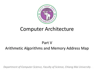
Computer Architecture Part IV BUS System for Registers and Arithmetic Circuits Department of Computer Science, Faculty of Science, Chiang Mai University
Outline Bus and Memory Transfers Binary Adder Binary Adder-Subtractor Binary Incrementer Arithmetic Circuit 2 204231: Computer Organization and Architecture
Bus and Memory Transfers An efficient scheme for transferring information between registers in a multiple-register configuration is a common bus system. A bus structure consists of a set of common lines, one for each bit of a register, through which binary information is transferred one at a time. Control signals determine which register is selected by the bus during each particular register transfer. 3 204231: Computer Organization and Architecture
Bus System for Four Registers Each register has four bits, numbered 0 through 3. The bus consists of four 4 x 1 multiplexers each having four data inputs, 0 through 3, and two selection inputs, S1and S0. We use labels to show the connections from the outputs of the registers to the inputs of the multiplexers. The diagram show that the bits in the same significant position in each register are connected to the data inputs of one multiplexer to form one line of the bus. 4 204231: Computer Organization and Architecture
Bus System for Four Registers 5 204231: Computer Organization and Architecture
Bus Selection The two selection lines S1and S0are connected to the selection inputs of all four multiplexers. When S1S0= 00, the 0 data inputs of all four multiplexers are selected and applied to the outputs that form the bus. This causes the bus lines to receive the content of register A since the outputs of this register are connected to the 0 data inputs of the multiplexers. 6 204231: Computer Organization and Architecture
Function Table for Bus 7 204231: Computer Organization and Architecture
Three-State Bus Buffers It is distinguished from a normal buffer by having both a normal input and a control input. The control input determines the output state. When the control input is equal to 1, the output is enabled and the gate behaves like any conventional buffer, with the output equal to the normal input. When the control input is 0, the output is disabled and the gate goes to a high-impedance state of a three-state gate provides a special feature not available in other gates. 8 204231: Computer Organization and Architecture
Graphic Symbols for Three-State Buffer 9 204231: Computer Organization and Architecture
Bus Line with Three State-Buffers The outputs of four buffers are connected together to form a single bus line. The control inputs to the buffers determine which of the four normal inputs will communicate with the bus line. No more than one buffer may be in the active state at any given time. 10 204231: Computer Organization and Architecture
Bus Line with Three State-Buffers 11 204231: Computer Organization and Architecture
Binary Adder The digital circuit that generates the arithmetic sum of two binary numbers of any length is called a binary adder. The binary adder is constructed with full- adder circuits connected in cascade, with the output carry from one full-adder connected to the input carry of the next full-adder. 12 204231: Computer Organization and Architecture
4-bit Binary Adder 13 204231: Computer Organization and Architecture
4-bit Adder-Subtractor When M = 0 the circuit is and adder and when M = 1 the circuit becomes a subtractor. Each exclusive-OR gate receives input M and one of the inputs of B. When M = 0, we have B ex-OR with 0 equal to B. The full-adders receive the value of B, the input carry is 0, and the circuit performs A plus B. 14 204231: Computer Organization and Architecture
4-bit Adder-Subtractor When M = 1, we have B ex-OR with 1 = B and C0= 1. The B inputs are all complemented and a 1 is added through the input carry. The circuit performs the operation A B. 15 204231: Computer Organization and Architecture
4-bit Adder-Subtractor 16 204231: Computer Organization and Architecture
4-bit Binary Incrementer One of the inputs to the least significant half- adder is connected to logic-1 and the other input is connected to the least significant bit of the number to be incremented. The output carry from one half-adder is connected to one of the inputs of the next-higher-order half- adder. The circuit receives the four bits from A0through A3, adds one to it. And generates the incremented outputs in S0through S3. 17 204231: Computer Organization and Architecture
4-bit Binary Incrementer 18 204231: Computer Organization and Architecture
4-bit Arithmetic Circuit It has four full-adder circuits that constitute the 4-bit adder and four multiplexers for choosing different operations. There are two 4-bit inputs A and B and a 4-bit output D. The four inputs from A go directly to the X inputs of the binary adder. Each of the four inputs from B are connected to the data inputs of the multiplexers. 19 204231: Computer Organization and Architecture
4-Bit Arithmetic Circuit The multiplexers data inputs also receive the complement of B. The other two data inputs are connected to logic- 0 and logic-1. The four multiplexers are controlled by two selection inputs, S1and S0. The input carry Cingoes to the carry input of the FA n the least significant position. The other carries are connected from one stage to the next. 20 204231: Computer Organization and Architecture
4-BitArithmeticCircuit 21 204231: Computer Organization and Architecture
Arithmetic Circuit Function Table The output of the binary adder is calculated from the following arithmetic sum: D = A + Y + Cin A is the 4-bit binary number at the X inputs and Y is the 4-bit binary number at the Y inputs of the binary adder. Cinis the input carry, which can be equal to 0 or 1. By controlling the value of Y with the two selection inputs S1 and S0 and making Cinequal to 0 or 1, it is possible to generate the eight arithmetic microoperations. 22 204231: Computer Organization and Architecture
Arithmetic Circuit Function Table 23 204231: Computer Organization and Architecture
Reference M. Moris Mano, Computer System Architecture, 3rded. NJ: Prentice Hall, 1992. 24 204231: Computer Organization and Architecture