Understanding Basic Input/Output Operations in Computer Organization

 undefined

C
o
m
p
u
t
e
r
O
r
g
a
n
i
z
a
t
i
o
n
2
0
1
5
-
2
0
1
6
1
Input/Output
2
B
a
s
i
c
I
n
p
u
t
/
O
u
t
p
u
t
O
p
e
r
a
t
i
o
n
s
•
Input/Output
operations which transfer data from the
processor or memory to and from the real world are essential.
•
In general, the rate of transfer from any input device to the
processor, or from the processor to any output device is likely
to the slower than the speed of a processor.
•
The difference in speed makes it necessary to create mechanisms
to synchronize the data transfer between them.
3
B
a
s
i
c
I
n
p
u
t
/
O
u
t
p
u
t
O
p
e
r
a
t
i
o
n
s
(
c
o
n
t
.
)
•
Let us consider a simple task of reading a character from a keyboard
and displaying that character on a display screen.
•
A simple way of performing the task is called
program-controlled I/O
.
•
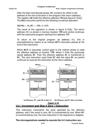
There are two separate blocks of instructions in the
I/O
program
that perform this task:
•
One block of instructions transfers the character into the processor.
•
Another block of instructions causes the character to be displayed.
4
B
a
s
i
c
I
n
p
u
t
/
O
u
t
p
u
t
o
p
e
r
a
t
i
o
n
s
(
c
o
n
t
.
)
D
A
T
A
I
N
D
A
T
A
O
U
T
S
I
N
S
O
U
T
K
e
y
b
o
a
r
d
D
i
s
p
l
a
y
B
u
s
P
r
o
c
e
s
s
o
r
Input:
•
When a key is struck on the keyboard, an 8-bit character code is stored in the buffer
register
DATAIN
.
•
A status control flag
SIN
is set to 1 to indicate that a valid character is in
DATAIN
.
•
A program monitors
SIN
, and when
SIN
is set to
1
, it reads the contents of
DATAIN
.
•
When the character is transferred to the processor,
SIN
is automatically cleared.
•
Initial state of
SIN
is
0
.
5
B
a
s
i
c
I
n
p
u
t
/
O
u
t
p
u
t
o
p
e
r
a
t
i
o
n
s
(
c
o
n
t
.
)
D
A
T
A
I
N
D
A
T
A
O
U
T
S
I
N
S
O
U
T
K
e
y
b
o
a
r
d
D
i
s
p
l
a
y
B
u
s
P
r
o
c
e
s
s
o
r
Output:
•
When
SOUT
is equal to
1
, the display is ready to receive a character.
•
A program monitors
SOUT
, and when
SOUT
is set to
1
, the processor transfers a
character code to the buffer
DATAOUT
.
•
Transfer of a character code to
DATAOUT
clears
SOUT
to
0
.
•
Initial state of
SOUT
is
1
.
6
B
a
s
i
c
I
n
p
u
t
/
O
u
t
p
u
t
o
p
e
r
a
t
i
o
n
s
(
c
o
n
t
.
)
•
Buffer registers
DATAIN
and
DATAOUT
, and status flags
SIN
and
SOUT
are part of a circuitry known as
device interface.
•
To perform
I/O
transfers, we need machine instructions to:
•
Monitor the status of the status registers (
SIN
and
SOUT
).
•
Transfer data among the
I/O
devices and the processor.
•
Instructions have similar format to the instructions used for moving
data between the processor and the memory.
7
A
c
c
e
s
s
i
n
g
I
/
O
d
e
v
i
c
e
s
•
Multiple
I/O
devices may be connected to the
processor
and the
memory
via a
bus
.
•
Bus
consists of three sets of lines to carry
address
,
data
and
control signals
.
•
Each
I/O
device is assigned an unique
address
.
•
To access an
I/O
device, the
processor
places the
address
on the
address lines
.
•
The device recognizes the
address
, and responds to the
control signals
.
8
A
c
c
e
s
s
i
n
g
I
/
O
d
e
v
i
c
e
s
(
c
o
n
t
.
)
•
I/O
device is connected to the bus using an
I/O
interface circuit which has:
Address decoder
,
control circuit
, and
data
and
status
registers.
•
Address decoder
decodes the address placed on the
address lines
thus enabling
the device to recognize its
address
(each device has a unique
address
).
•
Data
register (
DATAIN
and
DATAOUT
)
holds the
data
being transferred to or
from the
processor
.
•
Status
register (
SIN
and
SOUT
)
holds information necessary for the operation
of the
I/O
device.
•
Data
and
status
registers are connected to the
data
lines.
•
control circuit
receive and transmit the control signals through the control line.
9
A
c
c
e
s
s
i
n
g
I
/
O
d
e
v
i
c
e
s
(
c
o
n
t
.
)
10
10
A
c
c
e
s
s
i
n
g
I
/
O
d
e
v
i
c
e
s
(
c
o
n
t
.
)
11
11
Basic Input/Output Operations are essential functions in computer systems that involve transferring data between processors and external devices like keyboards and displays. This task requires synchronization mechanisms due to differences in processing speeds. The process involves reading characters from input devices, transferring them to the processor, and displaying them on output devices using program-controlled I/O techniques. Device interfaces include buffer registers and status flags like SIN and SOUT, which play a crucial role in data transfer. Machine instructions are used to monitor status registers and transfer data between I/O devices and the processor.

Download Presentation

Please find below an Image/Link to download the presentation.
The content on the website is provided AS IS for your information and personal use only. It may not be sold, licensed, or shared on other websites without obtaining consent from the author. Download presentation by click this link. If you encounter any issues during the download, it is possible that the publisher has removed the file from their server.
E N D
Presentation Transcript
Computer Organization 2015 - 2016 1
Basic Input/Output Operations Input/Output operations which transfer data from the processor or memory to and from the real world are essential. In general, the rate of transfer from any input device to the processor, or from the processor to any output device is likely to the slower than the speed of a processor. The difference in speed makes it necessary to create mechanisms to synchronize the data transfer between them. 3
Basic Input/Output Operations (cont.) Let us consider a simple task of reading a character from a keyboard and displaying that character on a display screen. A simple way of performing the task is called program-controlled I/O. There are two separate blocks of instructions in the I/O program that perform this task: One block of instructions transfers the character into the processor. Another block of instructions causes the character to be displayed. 4
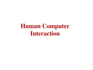
Basic Input/Output operations (cont.) Bus Processor D AT AIN D A TA OUT SIN SOUT Ke yboard Display Input: When a key is struck on the keyboard, an 8-bit character code is stored in the buffer register DATAIN. A status control flag SIN is set to 1 to indicate that a valid character is in DATAIN. A program monitors SIN, and when SIN is set to 1, it reads the contents of DATAIN. When the character is transferred to the processor, SIN is automatically cleared. Initial state of SIN is 0. 5
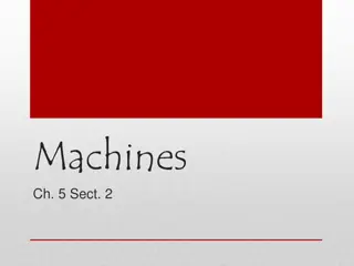
Basic Input/Output operations (cont.) Bus Processor D AT AIN D A TA OUT SIN SOUT Ke yboard Display Output: When SOUT is equal to 1, the display is ready to receive a character. A program monitors SOUT, and when SOUT is set to 1, the processor transfers a character code to the buffer DATAOUT. Transfer of a character code to DATAOUT clears SOUT to 0. Initial state of SOUT is 1. 6
Basic Input/Output operations (cont.) Buffer registers DATAIN and DATAOUT, and status flags SIN and SOUT are part of a circuitry known as device interface. To perform I/O transfers, we need machine instructions to: Monitor the status of the status registers (SIN and SOUT). Transfer data among the I/O devices and the processor. Instructions have similar format to the instructions used for moving data between the processor and the memory. 7
Accessing I/O devices Processor Memory Bus I/O de vice 1 I/O de vice n Multiple I/O devices may be connected to the processor and the memory via a bus. Bus consists of three sets of lines to carry address, data and control signals. Each I/O device is assigned an unique address. To access an I/O device, the processor places the address on the address lines. The device recognizes the address, and responds to the control signals. 8
Accessing I/O devices (cont.) I/O device is connected to the bus using an I/O interface circuit which has: Address decoder, control circuit, and data and status registers. Address decoder decodes the address placed on the address lines thus enabling the device to recognize its address (each device has a unique address). Data register (DATAIN and DATAOUT) holds the data being transferred to or from the processor. Status register (SIN and SOUT) holds information necessary for the operation of the I/O device. Data and status registers are connected to the data lines. control circuit receive and transmit the control signals through the control line. 9
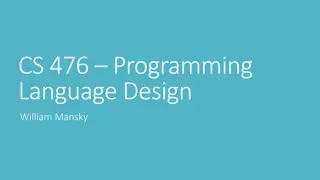
Accessing I/O devices (cont.) Address lines Bus Data lines Control lines Address Control circuits Data and status registers I/O int erface decoder Input devices 10
Accessing I/O devices (cont.) Address lines Bus Data lines Control lines Address Control circuits Data and status registers I/O int erface decoder Output devices 11


")
")
")
")

")
")
")