Understanding Flag Registers in Microprocessor 8086
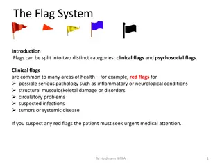
This content discusses the flag registers in the Microprocessor 8086, covering conditional flags such as Carry Flag (CF), Auxiliary Flag (AF), Parity Flag (PF), Zero Flag (ZF), Sign Flag (SF), and Overflow Flag (OF), as well as control flags including Trap Flag (TP), Interrupt Flag (IF), and Direction Flag (DF). These flags play a crucial role in indicating arithmetic and logical operations' results and controlling the execution unit's functions.
Download Presentation

Please find below an Image/Link to download the presentation.
The content on the website is provided AS IS for your information and personal use only. It may not be sold, licensed, or shared on other websites without obtaining consent from the author. Download presentation by click this link. If you encounter any issues during the download, it is possible that the publisher has removed the file from their server.
E N D
Presentation Transcript
Computer Architecture Lecture Four . / / . Chapter two\ Microprocessor 8086 /
2 4. Flag Registers (Cont.) a) Conditional Flags b) Control Flags
3 a) Conditional Flags Conditional flags represent result of last arithmetic or logical instruction executed. Conditional flags are as follows: 1. Carry Flag (CF): This flag indicates an overflow condition for unsigned integer arithmetic. It is also used in multiple-precision arithmetic. 2. Auxiliary Flag (AF): If an operation performed in ALU generates a carry/barrow from lower nibble (i.e. D0 D3) to upper nibble (i.e. D4 D7), the AF flag is set i.e. carry given by D3 bit to D4 is AF flag. This is not a general-purpose flag, it is used internally by the processor to perform Binary to BCD conversion. 3. Parity Flag (PF): This flag is used to indicate the parity of result. If lower order 8- bits of the result contains even number of 1 s, the Parity Flag is set and for odd number of 1 s, the Parity Flag is reset.
4 a) Conditional Flags 4. Zero Flag (ZF): It is set; if the result of arithmetic or logical operation is zero else it is reset. 5. Sign Flag (SF): In sign magnitude format the sign of number is indicated by MSB bit. If the result of operation is negative, sign flag is set. 6. Overflow Flag (OF): It occurs when signed numbers are added or subtracted. An OF indicates that the result has exceeded the capacity of machine.
5 b) Control Flags Control flags are set or reset deliberately to control the operations of the execution unit. Control flags are as follows: 1. Trap Flag (TP): 2. Interrupt Flag (IF): 3. Direction Flag (DF):
6 1. Trap Flag (TP): a. It is used for single step control. b. It allows user to execute one instruction of a program at a time for debugging. c. When trap flag is set, program can be run in single step mode.
7 2. Interrupt Flag (IF): a. It is an interrupt enable/disable flag. b. If it is set, the maskable interrupt of 8086 is enabled and if it is reset, the interrupt is disabled. c. It can be set by executing instruction sit and can be cleared by executing CLI instruction.
8 3. Direction Flag (DF): a. It is used in string operation. b. If it is set, string bytes are accessed from higher memory address to lower memory address. c. When it is reset, the string bytes are accessed from lower memory address to higher memory address.
9 ***** Examples of flag registers***** First example MOV BH,38H ADD BH,2FH 38 0011 1000 2F 0010 1111 87 0110 0111 CF=0 PF=0 AF=1 ZF=0 SF=0
10 ***** Examples of flag registers***** Second example Show how flag registers is affected by MOV AX,34F5H; AX=34F5H ADD AX,95EBH; AX=CAE0H 34F5 0011 0100 1111 0101 95EB 1001 0101 1110 1011 CAE0 1100 1010 1110 0000 CF=0 PF=1 AF=1 ZF=0 SF=1
11 The EU contains: - 1. ALU (Arithmetic & Logic Unit): 2. Registers 3. Control unit
12 3. Control unit :- Control Unit Functions : The control unit (CU) is a component of a CPU that directs the operation of the processor. It tells the computer's memory, arithmetic/logic unit(ALU) and input - output devices (I/O) How to respond to a program's instructions ? It directs the operation of the other units by providing timing and control signals. All computer resources are managed by the CU (Control Unit). It directs the flow of data between the CPU and the other devices. The control unit communicates / interact with ALU and main memory. Control unit generates the control signals to perform the operations. It controls the transmission between processor, memory and the various peripherals. It also instructs the ALU , which operation should be performed on data.
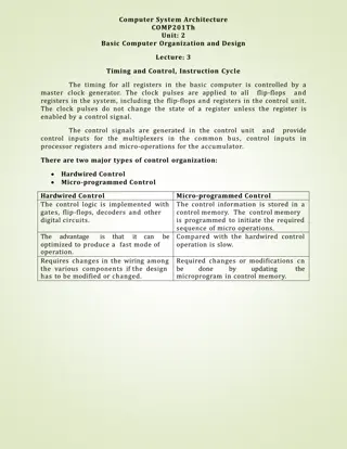
13 Design of Control Unit :- Control unit can be designed by two methods : 1. Hardwired Control Unit 2. Micro-Programmed Control Unit.
15 1. Hardwired Control Unit : It is implemented with the help of Physical components which is Hardwired (gates, flip flops, decoders) in the hardware. The inputs to control unit are the instruction register, flags, timing signals. If design is modified or changed, all the combinational circuits should be modified which is a very difficult task. The sequence of the operation carried out by this machine is determined by wiring of the logic elements so, it is known as Hardwired .
16 2. Micro-programmed Control Unit : It is implemented by using Programming approach. A sequence of micro operations is carried out by executing a program which consist of micro-instructions. In this, any modifications or changes can be done by updating the micro program in the control memory which is done by programmer. In this ,Control signals are generated by a program. Its speed is slow because of the time it takes to fetch microinstructions from control memory.
18 Microprocessor - 8086 Addressing Modes: The different ways in which a source operand is denoted in an instruction is known as addressing modes. There are 8 different addressing modes in 8086 programming : - 1- Immediate addressing mode : The addressing mode in which the data operand is a part of the instruction itself is known as immediate addressing mode. Example MOV CX, 4929 H ADD AX, 2387 H MOV AL, FFH
19 2- Register addressing mode : It means that the register is the source of an operand for an instruction. Example MOV CX, AX )copies the contents of the 16-bit AX register into the 16-bit CX register), ADD BX, AX 3- Direct addressing mode : The addressing mode in which the effective address of the memory location is written directly in the instruction. Example MOV AX, [1592H] MOV AL, [0300H]
20 4- Register indirect addressing mode : This addressing mode allows data to be addressed at any memory location through an offset address held in any of the following registers: BP, BX, DI & SI. Example MOV AX, [BX] ) Suppose the register BX contains 4895H, then the contents 4895H are moved to AX ( ADD CX, {BX} 5- Based addressing mode : In this addressing mode, the offset address of the operand is given by the sum of contents of the BX/BP registers and 8-bit/16-bit displacement. Example MOV DX, [BX+04] ADD CL, [BX+08]
21 6- Indexed addressing mode : In this addressing mode, the operands offset address is found by adding the contents of SI or DI register and 8-bit/16-bit displacements. Example MOV BX, [SI+16] ADD AL, [DI+16] 7- Based-index addressing mode : In this addressing mode, the offset address of the operand is computed by summing the base register to the contents of an Index register. Example ADD CX, [AX+SI] MOV AX, [AX+DI]
22 8- Based indexed with displacement mode : In this addressing mode, the operands offset is computed by adding the base register contents. An Index registers contents and 8 or 16-bit displacement. Example MOV AX, [BX+DI+08] ADD CX, [BX+SI+16]
23 Homework Show how flag registers is affected by MOV AX,28E5H; AX=28E5H ADD AX,83ACH; AX=? 28E5 0010 1000 1110 0101 83AC 1000 0011 1010 1100 CF=? PF=? AF=? ZF=? SF=?


