Understanding Relay, Optoisolator, and Stepper Motor Interfacing with 8051 Microcontroller

Explore the fundamentals of relays, optoisolators, and stepper motors along with their interfacing with the 8051 microcontroller. Learn about relay characteristics, operation, optoisolator linking, and stepper motor control through programming examples in Assembly and C.
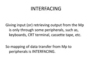
- Microcontroller Interfacing
- Relay Operation
- Optoisolator Interface
- Stepper Motor Control
- Embedded Systems

Download Presentation
Please find below an Image/Link to download the presentation.
The content on the website is provided AS IS for your information and personal use only. It may not be sold, licensed, or shared on other websites without obtaining consent from the author. Download presentation by click this link. If you encounter any issues during the download, it is possible that the publisher has removed the file from their server.
Presentation Transcript
THE 8051 MICROCONTROLLER & Embedded Systems Muhammad Ali Mazidi, Janice Mazidi & Rolin McKinlay
RELAY, OPTOISOLATOR, AND STEPPER MOTOR Chapter 15
Objectives Upon completion of this chapter, you will be able to: >> >> >> >> >> >> >> >> Describe the basic operation of a relay Interface the 8051 with a relay Describe the basic operation of an optoisolator Interface the 8051 with an optoisolator Describe the basic operation of a stepper motor Interface the 8051 with a stepper motor Code 8051 programs to control and operate a stepper motor Define stepper motor operation in terms of step angle, steps per revolution, tooth pitch, rotation speed, and RPM
Objectives Stepper motor control and 8051 interfacing with relays, optoisolators, and stepper motors, Section 15.1, the basics of relays and optoisolators and their interfacing with the 8051, Section 15.2, stepper motor interfacing with the 8051, Both Assembly and C is used in the programming examples
Table 15-1: Selected DIPRelay Characteristics (www.Jameco.com) Part No. 106462CP 138430CP 106471CP 138448CP 129875CP Contact Form SPST-NO SPST-NO SPST-NO SPST-NO DPDT Coil Volts 5VDC 5VDC 12VDC 12VDC 5VDC Coil Ohms 500 500 1000 1000 62.5 Contact Volts-Current 100VDC-0.5A 100VDC-0.5A 100VDC-0.5A 100VDC-0.5A 30VDC-1A
Table 15-2: Selected Solid-State Relay Characteristics (www.Jameco.com) Part No. 143058CP 139053CP 162341CP 172591CP 175222CP 176647CP Contact Style SPST SPST SPST SPST SPST SPST Control Volts 4-32VDC 3-32VDC 3-32VDC 3-32VDC 3-32VDC 3-32VDC Contact Volts 240VAC 240VAC 240VAC 60VDC 60VDC 120VDC Contact Current 3A 25A 10A 2A 4A 5A
Describe the 8051 connection to the stepper motor of Figure 15-9 and code a program to rotate it continuously. Example 15-1 Solution: The following steps show the 8051 connection to the stepper motor and its programming. 1.Use an ohmmeter to measure the resistance of the leads. This should identify which COM leads are connected to which winding leads. 2. The common wire(s) are connected to the positive side of the motor's power supply. In many motors, +5 V is sufficient. 3. The four leads of the stator winding are controlled by four bits of the 8051 port (P1.0 - P1.3). However, since the 8051 lacks sufficient current to drive the stepper motor windings, we must use a driver such as the ULN2003 to energize the stator. Instead of the ULN2003, we could have used transistors as drivers, as shown in Figure 17-9. However, notice that if transistors are used as drivers, we must also use diodes to take care of inductive current generated when the coil is turned off. One reason that using the ULN2003 is preferable to the use of transistors as drivers is that the ULN2003 has an internal diode to take care of back EMF. BACK: MOV MOV P1,A RR ACALL DELAY SJMP A,#66H ;load step sequence ;issue sequence to motor A ;wait BACK ;rotate right clockwise ;keep going DELAY H1: H2: ... Change the value of DELAY to set the speed of rotation. We can use the single-bit instructions SETB and CLR instead of RR A to create the sequences. MOV MOV DJNZ DJNZ RET R2,#100 R3,#255 R3,H2 R2,H1
Example 15-2 Give the number of times the four-step sequence in Table 15-3 must be applied to a stepper motor to make an 80-degree move if the motor has a 2-degree step angle. Solution: A motor with a 2-degree step angle has the following characteristics: Step angle: 2 degrees Number of rotor teeth: 45 To move the rotor 80 degrees, we need to send 10 consecutive four-step sequences, since 10 x 4 steps x 2 degrees = 80 degrees. Steps per revolution: Movement per 4-step sequence: 8 degrees 180
Table 15-7: Selected Solid-State Relay Characteristics (www.Jameco.com) Part No. 151861CP 171601CP 164056CP Step Angle 7.5 3.6 7.5 Drive System Volts Phase Resistance Current unipolar 5 V 9 ohms unipolar 7 V 20 ohms bipolar 5 V 6 mA 550 mA 350 mA 800 mA
Figure 15-11. Using Transistors for Stepper Motor Driver
Example 15-3 A switch is connected to pin P2.7. Write a program to monitor the status of SW and perform the following: (a) If SW = 0, the stepper motor moves clockwise. (b) If SW = 1, the stepper motor moves counterclockwise. Solution: ORG 0H P2.7 A, #66H P1, A ;starting address ;make an input ;starting phase value ;send value to port MAIN: SETB TURN: CW: MOV MOV JNB RR ACALL DELAY MOV P1,A SJMP TURN RL A ACALL DELAY MOV P1,A SJMP TURN P2.7, CW A ;write value to port ;repeat ;rotate left ;call delay ;write value to port ;repeat ;check switch result ;rotate right ;call delay DELAY: H1: H2: MOV MOV DJNZ DJNZ RET END R2, #100 R3, #255 R3, H2 R2,H1
#include <reg.h> sbit SW=P2^7; void main() { SW = 1; while(1) { if(SW == 0) { P1 = 0x66; MSDelay(100); P1 = 0xCC; MSDelay(100); P1 = 0x99; MSDelay(100); P1 = 0x33; MSDelay(100); } else { P1 = 0x66; MSDelay(100); P1 = 0x33; MSDelay(100); P1 = 0x99; MSDelay(100); P1 = 0xCC; MSDelay(100); } } } void MSDelay(unsigned int value) { unsigned int x, y; for(x=0;x<1275;x++) for(y=0;y<value;y++); } Solution: Example 15-4 A switch is connected to pin P2.7. Write a C program to monitor the status of SW and perform the following: (a) If SW = 0, the stepper motor moves clockwise. (b) If SW = 1, the stepper motor moves counterclockwise.