Understanding Three-Phase Power Electronics Circuits

Dr. Unnikrishnan P.C.
Professor, EEE
E
E
3
0
5
P
o
w
e
r
E
l
e
c
t
r
o
n
i
c
s
3
-
p
h
a
s
e
H
a
l
f
-
w
a
v
e
c
o
n
t
r
o
l
l
e
d
r
e
c
t
i
f
i
e
r
w
i
t
h
R
l
o
a
d
•
i
s
m
e
a
s
u
r
e
d
f
r
o
m
t
h
e
p
o
i
n
t
o
f
n
a
t
u
r
a
l
c
o
m
m
u
t
a
t
i
o
n
•
The only difference of this circuit is that the outgoing
Thyristor keeps conducting till the incoming thyristor is
triggered.
•
Each device conducts
for 120
•
Each phase supplies power for
120
.
•
A positive voltage across the blocking thyristor is possible.
•
Continuous output voltage(0<α<30
°
)
•
Discontinuous output voltage (30
°
<α<150
°
)
3
-
p
h
a
s
e
H
a
l
f
-
w
a
v
e
c
o
n
t
r
o
l
l
e
d
r
e
c
t
i
f
i
e
r
w
i
t
h
R
l
o
a
d
T
h
r
e
e
P
h
a
s
e
F
u
l
l
y
C
o
n
t
r
o
l
l
e
d
B
r
i
d
g
e
C
o
n
v
e
r
t
e
r
w
i
t
h
R
L
o
a
d
•
T
1
, T
3
, T
5
: Common
Cathode Configuration
•
T
2
, T
4
, T
6
: Common
Anode Configuration
•
I
f
a
l
l
a
r
e
d
i
o
d
e
s
,
c
h
a
n
g
e
o
v
e
r
t
a
k
e
s
p
l
a
c
e
a
t
X
,
Y
,
Z
a
n
d
P
,
Q
,
R
•
T
5
T
1
takes place at X
•
T
6
T
2
takes place at P
= 30
T
h
r
e
e
P
h
a
s
e
F
u
l
l
y
C
o
n
t
r
o
l
l
e
d
B
r
i
d
g
e
C
o
n
v
e
r
t
e
r
w
i
t
h
R
-
L
-
E
L
o
a
d
For any current to flow in the load at least
one device from the top group (T
1
, T
3
, T
5
)
and one from the bottom group (T
2
, T
4
,
T
6
) must conduct.
Thyristors are fired in the sequence
T
1
→ T
2
→ T
3
→ T
4
→ T
5
→ T
6
→ T
1
with
60° interval between each firing.
Thyristors on the same phase leg are fired at an interval of 180° and
hence can not conduct simultaneously.
This leaves only six possible conduction mode for the converter in the
continuous conduction mode T
1
T
2
, T
2
T
3
, T
3
T
4
,
T
4
T
5
, T
5
T
6
, T
6
T
1
.
T
h
r
e
e
P
h
a
s
e
F
u
l
l
y
C
o
n
t
r
o
l
l
e
d
B
r
i
d
g
e
C
o
n
v
e
r
t
e
r
w
i
t
h
R
L
o
a
d
(
=
0
)
T
h
r
e
e
P
h
a
s
e
F
u
l
l
y
C
o
n
t
r
o
l
l
e
d
B
r
i
d
g
e
C
o
n
v
e
r
t
e
r
w
i
t
h
R
L
o
a
d
•
=0 is equivalent to an uncontrolled full
wave bridge
•
Thyristors should be fired at X,Y Z and
P,Q,R
•
Each device conducts
for 120
•
Each phase supplies power for
240
in a
cycle provided load current is continuous.
•
6 Pulses per Cycle, each of 60
.
•
At any time only two phase supply power
to the load and one phase is open.
T
h
r
e
e
P
h
a
s
e
F
u
l
l
y
C
o
n
t
r
o
l
l
e
d
B
r
i
d
g
e
C
o
n
v
e
r
t
e
r
w
i
t
h
R
L
o
a
d
(
=
3
0
)
T
h
r
e
e
P
h
a
s
e
F
u
l
l
y
C
o
n
t
r
o
l
l
e
d
B
r
i
d
g
e
C
o
n
v
e
r
t
e
r
w
i
t
h
R
L
o
a
d
(
=
6
0
)
T
h
r
e
e
P
h
a
s
e
F
u
l
l
y
C
o
n
t
r
o
l
l
e
d
B
r
i
d
g
e
C
o
n
v
e
r
t
e
r
w
i
t
h
R
L
o
a
d
(
=
6
0
)
For what firing angle,
,
the current through the load
becomes discontinuous
?
F
o
r
=
0
V
o
v
a
r
i
e
s
f
r
o
m
1
.
5
V
t
o
1
.
7
3
2
V
o
l
t
s
F
o
r
=
3
0
V
o
v
a
r
i
e
s
f
r
o
m
0
.
8
6
6
V
t
o
1
.
7
3
2
V
o
l
t
s
F
o
r
=
6
0
V
o
v
a
r
i
e
s
f
r
o
m
0
V
t
o
1
.
5
V
o
l
t
s
A
t
=
6
0
,
V
o
t
o
u
c
h
e
s
t
h
e
X
-
a
x
i
s
,
s
o
a
s
t
h
e
l
o
a
d
c
u
r
r
e
n
t
.
S
o
b
e
y
o
n
d
=
6
0
l
o
a
d
c
u
r
r
e
n
t
b
e
c
o
m
e
s
d
i
s
c
o
n
t
i
n
u
o
u
s
.
T
h
r
e
e
P
h
a
s
e
F
u
l
l
y
C
o
n
t
r
o
l
l
e
d
B
r
i
d
g
e
C
o
n
v
e
r
t
e
r
w
i
t
h
R
L
o
a
d
(
=
9
0
)
T
h
r
e
e
P
h
a
s
e
F
u
l
l
y
C
o
n
t
r
o
l
l
e
d
B
r
i
d
g
e
C
o
n
v
e
r
t
e
r
w
i
t
h
R
L
o
a
d
(
=
9
0
)
F
o
r
=
9
0
A
v
e
r
a
g
e
v
a
l
u
e
o
f
t
h
e
o
u
t
p
u
t
v
o
l
t
a
g
e
,
V
o
,
=
0
b
u
t
t
h
e
c
u
r
r
e
n
t
i
s
c
o
n
t
i
n
u
o
u
s
.
W
h
e
n
i
s
t
h
i
s
p
o
s
s
i
b
l
e
?
This is possible only if the load is purely inductive. (The
average value of the voltage across an inductor is 0).
F
o
r
o
t
h
e
r
l
o
a
d
s
a
c
o
n
t
i
n
u
o
u
s
c
o
n
d
u
c
t
i
o
n
i
s
n
o
t
p
o
s
s
i
b
l
e
f
o
r
=
9
0
.
T
h
r
e
e
P
h
a
s
e
F
u
l
l
y
C
o
n
t
r
o
l
l
e
d
B
r
i
d
g
e
C
o
n
v
e
r
t
e
r
w
i
t
h
R
L
o
a
d
(
=
1
2
0
)
T
h
r
e
e
P
h
a
s
e
F
u
l
l
y
C
o
n
t
r
o
l
l
e
d
B
r
i
d
g
e
C
o
n
v
e
r
t
e
r
w
i
t
h
R
L
o
a
d
(
=
1
5
0
)
C
o
n
v
e
r
t
e
r
&
I
n
v
e
r
t
e
r
C
o
n
v
e
r
t
e
r
O
p
e
r
a
t
i
o
n
F
o
r
=
0
V
o
v
a
r
i
e
s
f
r
o
m
1
.
5
V
t
o
1
.
7
3
2
V
o
l
t
s
F
o
r
=
3
0
V
o
v
a
r
i
e
s
f
r
o
m
0
.
8
6
6
V
t
o
1
.
7
3
2
V
o
l
t
s
F
o
r
=
6
0
V
o
v
a
r
i
e
s
f
r
o
m
0
V
t
o
1
.
5
V
o
l
t
s
F
o
r
=
9
0
V
o
v
a
r
i
e
s
f
r
o
m
-
0
.
8
6
6
V
t
o
0
.
8
6
6
V
o
l
t
s
I
n
v
e
r
t
e
r
O
p
e
r
a
t
i
o
n
F
o
r
=
1
2
0
V
o
v
a
r
i
e
s
f
r
o
m
-
0
.
8
6
6
V
t
o
-
1
.
5
V
o
l
t
s
F
o
r
=
1
5
0
V
o
v
a
r
i
e
s
f
r
o
m
-
0
.
8
6
6
V
t
o
-
1
.
7
3
2
V
o
l
t
s
Q
u
e
s
t
i
o
n
A DC
motor (R-L-E Load) speed need to be controlled
using a single phase fully controlled converter. What
should be the values of
at starting and later to increase
speed?
The natural answer is
=90
and then keep on
decreasing.
At
=90
, the instantaneous value of the input is maximum
and if this is applied to the armature, a very high current
will pass through the armature and damage.
So the safe value of
is around
=150
and reduce it
slowly
C
o
m
p
a
r
i
s
o
n
o
f
v
a
r
i
o
u
s
c
o
n
v
e
r
t
e
r
s
The filter requirement reduces with increase in number of pulses
per cycle.
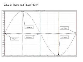
Dive into the world of three-phase power electronics circuits, including half-wave and fully controlled rectifiers with R loads. Explore the operation of these circuits, their conduction modes, firing sequences, and the equivalent of fully controlled bridge converters under different load conditions.

Download Presentation

Please find below an Image/Link to download the presentation.
The content on the website is provided AS IS for your information and personal use only. It may not be sold, licensed, or shared on other websites without obtaining consent from the author. Download presentation by click this link. If you encounter any issues during the download, it is possible that the publisher has removed the file from their server.
E N D
Presentation Transcript
EE305 Power Electronics Dr. Unnikrishnan P.C. Professor, EEE
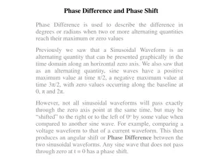
3-phase Half-wave controlled rectifier with R load is measured from the point of natural commutation
3-phase Half-wave controlled rectifier with R load The only difference of this circuit is that the outgoing Thyristor keeps conducting till the incoming thyristor is triggered. Each device conducts for 120 Each phase supplies power for 120 . A positive voltage across the blocking thyristor is possible. Continuous output voltage(0< <30 ) Discontinuous output voltage (30 < <150 )
Three Phase Fully Controlled Bridge Converter with R Load T1, T3, T5 : Common Cathode Configuration T2, T4, T6 : Common Anode Configuration If all are diodes, changeover takes place at X,Y,Z and P,Q,R T5 T1 takes place at X T6 T2 takes place at P
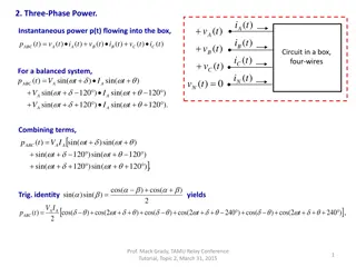
Three Phase Fully Controlled Bridge Converter with R-L-E Load For any current to flow in the load at least one device from the top group (T1, T3, T5) and one from the bottom group (T2, T4, T6) must conduct. Thyristors are fired in the sequence T1 T2 T3 T4 T5 T6 T1 with 60 interval between each firing. Thyristors on the same phase leg are fired at an interval of 180 and hence can not conduct simultaneously. This leaves only six possible conduction mode for the converter in the continuous conduction mode T1T2, T2T3, T3T4, T4T5, T5T6, T6T1.
Three Phase Fully Controlled Bridge Converter with R Load ( = 0 )
Three Phase Fully Controlled Bridge Converter with R Load =0 is equivalent to an uncontrolled full wave bridge Thyristors should be fired at X,Y Z and P,Q,R Each device conducts for 120 Each phase supplies power for 240 in a cycle provided load current is continuous. 6 Pulses per Cycle, each of 60 . At any time only two phase supply power to the load and one phase is open.
Three Phase Fully Controlled Bridge Converter with R Load ( = 30 )
Three Phase Fully Controlled Bridge Converter with R Load ( = 60 )
Three Phase Fully Controlled Bridge Converter with R Load ( = 60 ) For what firing angle, , the current through the load becomes discontinuous ? For =0 Vo varies from 1.5 V to 1.732 Volts For =30 Vo varies from 0.866 V to 1.732 Volts For =60 Vo varies from 0 V to 1.5 Volts At =60 , Vo touches the X-axis, so as the load current. So beyond =60 load current becomes discontinuous.
Three Phase Fully Controlled Bridge Converter with R Load ( = 90 )
Three Phase Fully Controlled Bridge Converter with R Load ( = 90 ) For =90 Average value of the output voltage,Vo ,=0 but the current is continuous. When is this possible? This is possible only if the load is purely inductive. (The average value of the voltage across an inductor is 0). For other loads a continuous conduction is not possible for =90 .
Three Phase Fully Controlled Bridge Converter with R Load ( = 120 )
Three Phase Fully Controlled Bridge Converter with R Load ( = 150 )
Converter & Inverter Converter Operation For =0 Vo varies from 1.5 V to 1.732 Volts For =30 Vo varies from 0.866 V to 1.732 Volts For =60 Vo varies from 0 V to 1.5 Volts For =90 Vo varies from -0.866 V to 0.866 Volts Inverter Operation For =120 Vo varies from -0.866 V to -1.5 Volts For =150 Vo varies from -0.866 V to -1.732 Volts
Question A DC motor (R-L-E Load) speed need to be controlled using a single phase fully controlled converter. What should be the values of at starting and later to increase speed? The natural answer is =90 and then keep on decreasing. At =90 , the instantaneous value of the input is maximum and if this is applied to the armature, a very high current will pass through the armature and damage. So the safe value of is around =150 and reduce it slowly
Comparison of various converters The filter requirement reduces with increase in number of pulses per cycle.