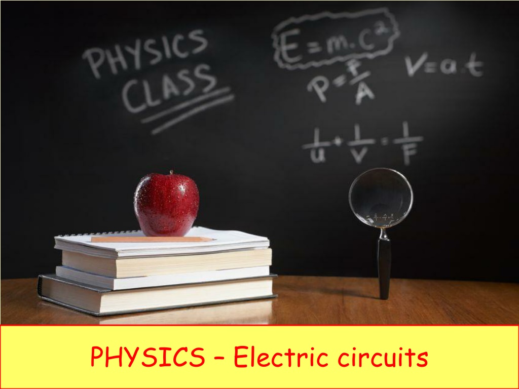
Comprehensive Guide to Electric Circuits and Circuit Diagram Interpretation
Explore the fundamentals of electric circuits, circuit components, and diagram interpretation. Learn about series and parallel circuits, resistors, sources, switches, transducers, and more. Discover how to calculate resistance, current, and potential difference in circuits. Gain insights into diodes, potentiometers, relays, and practical circuit applications like lighting systems and alarms.

Download Presentation

Please find below an Image/Link to download the presentation.
The content on the website is provided AS IS for your information and personal use only. It may not be sold, licensed, or shared on other websites without obtaining consent from the author. Download presentation by click this link. If you encounter any issues during the download, it is possible that the publisher has removed the file from their server.
E N D
Presentation Transcript
LEARNING OBJECTIVES Core Draw and interpret circuit diagrams containing sources, switches, resistors (fixed and variable), heaters, thermistors, light- dependent resistors, lamps, ammeters, voltmeters, galvanometers, magnetising coils, transformers, bells, fuses and relays Understand that the current at every point in a series circuit is the same Give the combined resistance of two or more resistors in series State that, for a parallel circuit, the current from the source is larger than the current in each branch State that the combined resistance of two resistors in parallel is less than that of either resistor by itself State the advantages of connecting lamps in parallel in a lighting circuit Describe the action of a variable potential divider (potentiometer) Describe the action of thermistors and light- dependent resistors and show understanding of their use as input transducers Describe the action of a relay and show understanding of its use in switching circuits Supplement Draw and interpret circuit diagrams containing diodes Calculate the combined e.m.f. of several sources in series Recall and use the fact that the sum of the p.d.s across the components in a series circuit is equal to the total p.d. across the supply Recall and use the fact that the current from the source is the sum of the currents in the separate branches of a parallel circuit Calculate the effective resistance of two resistors in parallel Describe the action of a diode and show understanding of its use as a rectifier Recognise and show understanding of circuits operating as light-sensitive switches and temperature-operated alarms (to include the use of a relay)
Draw and interpret circuit diagrams containing sources, switches, resistors (fixed and variable), heaters, thermistors, light-dependent resistors, lamps, ammeters, voltmeters, galvanometers, magnetising coils, transformers, bells, fuses and relays Draw and interpret circuit diagrams containing diodes
Draw and interpret circuit diagrams containing sources, switches, resistors (fixed and variable), heaters, thermistors, light-dependent resistors, lamps, ammeters, voltmeters, galvanometers, magnetising coils, transformers, bells, fuses and relays Draw and interpret circuit diagrams containing diodes
Draw and interpret circuit diagrams containing sources, switches, resistors (fixed and variable), heaters, thermistors, light-dependent resistors, lamps, ammeters, voltmeters, galvanometers, magnetising coils, transformers, bells, fuses and relays Draw and interpret circuit diagrams containing diodes Components
Draw and interpret circuit diagrams containing sources, switches, resistors (fixed and variable), heaters, thermistors, light-dependent resistors, lamps, ammeters, voltmeters, galvanometers, magnetising coils, transformers, bells, fuses and relays Draw and interpret circuit diagrams containing diodes Components Switch Resistor (fixed)
Draw and interpret circuit diagrams containing sources, switches, resistors (fixed and variable), heaters, thermistors, light-dependent resistors, lamps, ammeters, voltmeters, galvanometers, magnetising coils, transformers, bells, fuses and relays Draw and interpret circuit diagrams containing diodes Components Resistor (variable) Switch Resistor (fixed) Heater
Draw and interpret circuit diagrams containing sources, switches, resistors (fixed and variable), heaters, thermistors, light-dependent resistors, lamps, ammeters, voltmeters, galvanometers, magnetising coils, transformers, bells, fuses and relays Draw and interpret circuit diagrams containing diodes Components Resistor (variable) Cell Battery Heater
Draw and interpret circuit diagrams containing sources, switches, resistors (fixed and variable), heaters, thermistors, light-dependent resistors, lamps, ammeters, voltmeters, galvanometers, magnetising coils, transformers, bells, fuses and relays Draw and interpret circuit diagrams containing diodes Components Cell Thermistor Light dependent resistor (LDR) Battery
Draw and interpret circuit diagrams containing sources, switches, resistors (fixed and variable), heaters, thermistors, light-dependent resistors, lamps, ammeters, voltmeters, galvanometers, magnetising coils, transformers, bells, fuses and relays Draw and interpret circuit diagrams containing diodes Components Filament lamp Thermistor Filament lamp Light dependent resistor (LDR)
Draw and interpret circuit diagrams containing sources, switches, resistors (fixed and variable), heaters, thermistors, light-dependent resistors, lamps, ammeters, voltmeters, galvanometers, magnetising coils, transformers, bells, fuses and relays Draw and interpret circuit diagrams containing diodes Components Filament lamp Ammeter Filament lamp Voltmeter
Draw and interpret circuit diagrams containing sources, switches, resistors (fixed and variable), heaters, thermistors, light-dependent resistors, lamps, ammeters, voltmeters, galvanometers, magnetising coils, transformers, bells, fuses and relays Draw and interpret circuit diagrams containing diodes Components Ammeter Galvanometer Magnetising coil Voltmeter
Draw and interpret circuit diagrams containing sources, switches, resistors (fixed and variable), heaters, thermistors, light-dependent resistors, lamps, ammeters, voltmeters, galvanometers, magnetising coils, transformers, bells, fuses and relays Draw and interpret circuit diagrams containing diodes Components Transformer Galvanometer Magnetising coil Bell
Draw and interpret circuit diagrams containing sources, switches, resistors (fixed and variable), heaters, thermistors, light-dependent resistors, lamps, ammeters, voltmeters, galvanometers, magnetising coils, transformers, bells, fuses and relays Draw and interpret circuit diagrams containing diodes Components Fuse Transformer Relay (and switch) Bell
Draw and interpret circuit diagrams containing sources, switches, resistors (fixed and variable), heaters, thermistors, light-dependent resistors, lamps, ammeters, voltmeters, galvanometers, magnetising coils, transformers, bells, fuses and relays Draw and interpret circuit diagrams containing diodes Components DC Power Supply Fuse Relay (and switch) AC Power Supply
Draw and interpret circuit diagrams containing sources, switches, resistors (fixed and variable), heaters, thermistors, light-dependent resistors, lamps, ammeters, voltmeters, galvanometers, magnetising coils, transformers, bells, fuses and relays Draw and interpret circuit diagrams containing diodes Components Diode Light emitting diode Diodes only allow current to flow in one direction. They can be used to protect damage to polarised components.
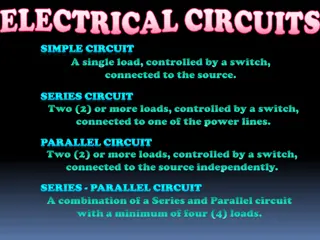
Series and Parallel Circuits Series Components are in a single loop, and the current flows from one to the next without any branches.
Series and Parallel Circuits Series Components are in a single loop, and the current flows from one to the next without any branches. If more bulbs are put into the circuit then the bulbs will be dimmer than before.
Series and Parallel Circuits Series Components are in a single loop, and the current flows from one to the next without any branches. If more bulbs are put into the circuit then the bulbs will be dimmer than before. If one bulb breaks then the circuit is broken and all components stop working.
Series and Parallel Circuits Series Parallel Components are connected on different branches of the wire Components are in a single loop, and the current flows from one to the next without any branches. If more bulbs are put into the circuit then the bulbs will be dimmer than before. If one bulb breaks then the circuit is broken and all components stop working.
Series and Parallel Circuits Series Parallel Components are connected on different branches of the wire. If more bulbs are added then the lamps stay bright they take full voltage. Components are in a single loop, and the current flows from one to the next without any branches. If more bulbs are put into the circuit then the bulbs will be dimmer than before. If one bulb breaks then the circuit is broken and all components stop working.
Series and Parallel Circuits Series Parallel Components are connected on different branches of the wire. If more bulbs are added then the lamps stay bright they take full voltage. If one bulb breaks the components on different branches keep working. Our home circuits are parallel. Components are in a single loop, and the current flows from one to the next without any branches. If more bulbs are put into the circuit then the bulbs will be dimmer than before. If one bulb breaks then the circuit is broken and all components stop working.
Current in Series and Parallel circuits Ammeters can be placed anywhere in a series circuit and will all give the same reading. http://www.bbc.co.uk/bitesize/ks3/science/energy_electricity_forces/electric_current_voltage/revision/6/
Current in Series and Parallel circuits In a parallel circuit the current through each component depends upon its resistance.
Current in Series and Parallel circuits In a parallel circuit the current through each component depends upon its resistance. 5.5A 1.5A 3A The total current flowing around the circuit is equal to the total of all the currents in the separate branches. 1A
Current in Series and Parallel circuits In a parallel circuit the current through each component depends upon its resistance. 5.5A 1.5A 3A The total current flowing around the circuit is equal to the total of all the currents in the separate branches. 1A A1 = A2 + A3 + A4
Current in Series and Parallel circuits In a parallel circuit the current through each component depends upon its resistance. 5.5A 1.5A 3A The total current flowing around the circuit is equal to the total of all the currents in the separate branches. 1A A1 = A2 + A3 + A4 5.5 = 1.5 + 3 + 1
Voltage is measured using a VOLTMETER Voltage in Series and Parallel circuits To measure the voltage across a component in a circuit the voltmeter must be placed in parallel with it.
Voltage is measured using a VOLTMETER Voltage in Series and Parallel circuits In a series circuit the total voltage (PD) of the supply is shared between the various components, so the voltages around a series circuit always add up to equal the source voltage.
Voltage is measured using a VOLTMETER Voltage in Series and Parallel circuits In a parallel circuit all components get the full source voltage, so the voltage is the same across all components In a series circuit the total voltage (PD) of the supply is shared between the various components, so the voltages around a series circuit always add up to equal the source voltage.
Resistance in Series and Parallel circuits In series If resistors are connected in series, the current through each resistor is the same. I1 = I2 = I3 I1 I2 I3
Resistance in Series and Parallel circuits In series If resistors are connected in series, the current through each resistor is the same. VT V1 V2 V3 I1 = I2 = I3 I1 I2 I3 If resistors are connected in series, the potential difference across all resistors is equal to the sum of the potential differences across each resistor. VT = V1 + V2 + V3
Resistance in Series and Parallel circuits In series If resistors are connected in series, the current through each resistor is the same. VT V1 R1 V2 R2 V3 R3 I1 = I2 = I3 I1 I2 I3 If resistors are connected in series, the potential difference across all resistors is equal to the sum of the potential differences across each resistor. The total resistance of a number of resistors in series is equal to the sum of all the individual resistances. RT = R1 + R2 + R3 VT = V1 + V2 + V3
Resistance in Series and Parallel circuits In parallel
Resistance in Series and Parallel circuits In parallel IT If resistors are connected in parallel, the total current is equal to the sum of the currents through each resistor. I1 I2 IT = I1 + I2 + I3 I3
Resistance in Series and Parallel circuits In parallel IT If resistors are connected in parallel, the total current is equal to the sum of the currents through each resistor. V1 I1 V2 I2 IT = I1 + I2 + I3 V3 I3 If resistors are connected in parallel, the potential difference across all resistors is the same. V1 = V2 = V3
Resistance in Series and Parallel circuits In parallel IT If resistors are connected in parallel, the total current is equal to the sum of the currents through each resistor. V1 I1 R1 V2 I2 IT = I1 + I2 + I3 R2 V3 I3 R3 If resistors are connected in parallel, the potential difference across all resistors is the same. The total resistance of a number of resistors in parallel is given by the formula: 1/RT = 1/R1 + 1/R2 + 1/R3 V1 = V2 = V3
Resistance in Series and Parallel circuits In parallel The total resistance of a number of resistors in parallel is given by the formula: R1 R2 1/RT = 1/R1 + 1/R2 + 1/R3 R3 For example, if: R1 = 18 R2 = 12 R3 = 6 1/RT = 1/18 + 1/12 + 1/6 = 2/36 + 3/36 + 6/36 = 11/36 RT = 36/11 = 3.27
LEARNING OBJECTIVES Core Draw and interpret circuit diagrams containing sources, switches, resistors (fixed and variable), heaters, thermistors, light- dependent resistors, lamps, ammeters, voltmeters, galvanometers, magnetising coils, transformers, bells, fuses and relays Understand that the current at every point in a series circuit is the same Give the combined resistance of two or more resistors in series State that, for a parallel circuit, the current from the source is larger than the current in each branch State that the combined resistance of two resistors in parallel is less than that of either resistor by itself State the advantages of connecting lamps in parallel in a lighting circuit Describe the action of a variable potential divider (potentiometer) Describe the action of thermistors and light- dependent resistors and show understanding of their use as input transducers Describe the action of a relay and show understanding of its use in switching circuits Supplement Draw and interpret circuit diagrams containing diodes Calculate the combined e.m.f. of several sources in series Recall and use the fact that the sum of the p.d.s across the components in a series circuit is equal to the total p.d. across the supply Recall and use the fact that the current from the source is the sum of the currents in the separate branches of a parallel circuit Calculate the effective resistance of two resistors in parallel Describe the action of a diode and show understanding of its use as a rectifier Recognise and show understanding of circuits operating as light-sensitive switches and temperature-operated alarms (to include the use of a relay)
What is a variable potential divider?
What is a variable potential divider? Potential dividers divide up the voltage within a circuit, so that parts of the circuit only receive the voltage they require. They usually consist of two or more resistors in series across a power supply.
What is a variable potential divider? Potential dividers divide up the voltage within a circuit, so that parts of the circuit only receive the voltage they require. They usually consist of two or more resistors in series across a power supply. 10 6V In this example, the lower resistor has half the total resistance of the two resistors, so its share of the voltage from the battery is also a half. 10 3V
What is a variable potential divider? If one of the resistors is replaced by a variable resistor then the output voltage can be varied. In this example, it can range from 0 to 3V, depending upon the setting of the variable resistor. 10 6V 0-10 k 0-3V A circuit such as this one could be used as a radio volume control.
What is a diode, and how does it rectify?