Understanding Computer Organization and Architecture
A computer system is a programmable digital electronics device that processes data as per program instructions to provide meaningful output. It comprises hardware and software components, with hardware being the physical parts and software essential for driving the hardware. Computer organization focuses on the structure and behavior of digital computers, covering basic hardware structure and peripheral devices. Computer architecture entails rules and methods governing computer functionality, management, and implementation, with divisions into Instruction Set Architecture (ISA), Micro Architecture, and System Design to balance performance, efficiency, cost, and reliability of computer systems.
- Computer Organization
- Computer Architecture
- System Design
- Instruction Set Architecture
- Hardware Components
Download Presentation

Please find below an Image/Link to download the presentation.
The content on the website is provided AS IS for your information and personal use only. It may not be sold, licensed, or shared on other websites without obtaining consent from the author. Download presentation by click this link. If you encounter any issues during the download, it is possible that the publisher has removed the file from their server.
E N D
Presentation Transcript
Computer Organization & Architecture Unit 1 Presented By : Mrs. Seema Ranga State Institute of Engineering & Technology, Nilokheri Department : Computer Engineering
INTRODUCTION TO COMPUTER SYSYTEM A computer system is defined as a digital electronics device that can be programmed to accept some inputs in terms of data, then process this data as per the program instructions and provide the output in the desired format that can be used for some meaningful work. The computer system is programmable. That means, the computer will perform the task only as per the program instructions. The computer system consist of both software components and hardware components. The hardware components are physical parts that we can touch and interact. Whereas, the software is essential to drive the hardware.
user input application software operating system output
Computer Organization The computer organization is concerned with the structure and behavior of digital computers. The main objective of this subject to understand the overall basic computer hardware structure, including the peripheral devices. In spite of variety and pace in the computer field, certain fundamental concepts apply consistently throughout. The application of these concepts depends upon the current state of technology and the price/performance objectives of the designer. The aim of the subject is to provide a through discussion of the fundamentals of computer organization and architecture and to relate these to contemporary design issues.
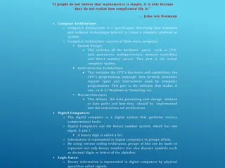
Computer Architecture Computer architecture can be defined as a set of rules and methods that describe the functionality, management and implementation of computers. To be precise, it is nothing but rules by which a system performs and operates. Sub-divisions Computer Architecture can be divided into mainly three categories, which are as follows Instruction set Architecture or ISA Whenever an instruction is given to processor, its role is to read and act accordingly. It allocates memory to instructions and also acts upon memory address mode (Direct Addressing mode or Indirect Addressing mode). Micro Architecture It describes how a particular processor will handle and implement instructions from ISA. System design It includes the other entire hardware component within the system such as virtualization, multiprocessing. Role of computer Architecture The main role of Computer Architecture is to balance the performance, efficiency, cost and reliability of a computer system.
For Example Instruction set architecture (ISA) acts as a bridge between computer's software and hardware. It works as a programmer's view of a machine. Computers can only understand binary language (i.e., 0, 1) and users understand high level language (i.e., if else, while, conditions, etc). So to communicate between user and computer, Instruction set Architecture plays a major role here, translating high level language to binary language. Structure Let us see the example structure of Computer Architecture as given below. Generally, computer architecture consists of the following Processor Memory Peripherals All the above parts are connected with the help of system bus, which consists of address bus, data bus and control bus.
Von Neumann Architecture Von-Neumann proposed his computer architecture design in 1945 which was later known as Von-Neumann Architecture. It consisted of a Control Unit, Arithmetic, and Logical Memory Unit (ALU), Registers and Inputs/Outputs. Von Neumann architecture is based on the stored-program computer concept, where instruction data and program data are stored in the same memory. This design is still used in most computers produced today. A Von Neumann-based computer: Uses a single processor Uses one memory for both instructions and data. Executes programs following the fetch-decode-execute cycle
Components of Von-Neumann Model: Central Processing Unit Buses Memory Unit
Central Processing Unit :The part of the Computer that performs the bulk of data processing operations is called the Central Processing Unit and is referred to as the CPU. The Central Processing Unit can also be defined as an electric circuit responsible for executing the instructions of a computer program. The CPU performs a variety of functions dictated by the type of instructions that are incorporated in the computer. Buses: Buses are the means by which information is shared between the registers in a multiple-register configuration system. A bus structure consists of a set of common lines, one for each bit of a register, through which binary information is transferred one at a time. Control signals determine which register is selected by the bus during each particular register transfer. Memory Unit: A memory unit is a collection of storage cells together with associated circuits needed to transfer information in and out of the storage. The memory stores binary information in groups of bits called words. The internal structure of a memory unit is specified by the number of words it contains and the number of bits in each word.
Early History Necessity is the mother of invention , famous saying formed the basis of modern computers ABACUS: Very first computing device ABACUS also called Soroban invented in 600 BC was the first computing device Napier Rods: Napier Rods was a card board multiplication calculator. It was designed in early 17th century
1642: Blaise Pascal, a French mathematician and philosopher, invented the first operating model of mechanical digital calculator using gears, called the Arithmetic Machine PASCALINE It was for addition, subtraction, and multiplication and division
Charles Babbage is The Father of Computers 1822: His great invention Difference Engine was to perform mathematical calculations It was fully automatic and commanded by a fixed instruction program 1842: The Analytical Engine was a automatic machine. It could do 60 addition per minute The idea of analytical engine served as a base of modern digital computers
1890: Dr. Herman Hollerith introduced the first electromechanical, punched- card data processing machine His company would eventually become International Business Machine (IBM) This paper based machine represents the origin of computer database software
1941: Conrad Zeus dorm Germany, introduced the first programmable computer It solved complex engineering equations It was also first to work on the binary system instead of decimal system
The computer has evolved from a large-sized simple calculating machine to a smaller but much more powerful machine. The evolution of computer to the current state is defined in terms of the generations of computer. Each generation of computer is designed based on a new technological development, resulting in better, cheaper and smaller computers that are more powerful, faster and efficient than their predecessors. 18
Currently, there are five generations of computer. In the following subsections, we will discuss the generations of computer in terms of the technology used by them (hardware and software), computing characteristics (speed, i.e., number of instructions executed per second), physical appearance, and their applications First Generation Computers (1940-1956) The first computers used vacuum tubes(a sealed glass tube containing a near-vacuum which allows the free passage of electric current.) for circuitry and magnetic drums for memory. They were often enormous and taking up entire room. First generation computers relied on machine language. 19
They were very expensive to operate and in addition to using a great deal of electricity, generated a lot of heat, which was often the cause of malfunctions(defect or breakdown). The UNIVAC and ENIAC computers are examples of first-generation computing devices. 20
Advantages : It was only electronic device First device to hold memory Disadvantages : Too bulky i.e large in size Vacuum tubes burn frequently They were producing heat Maintenance problems 21
Transistors replaced vacuum tubes and ushered in the second generation of computers. Second-generation computers moved from cryptic binary machine language to symbolic. High-level programming languages were also being developed at this time, such as early versions of COBOL and FORTRAN. These were also the first computers that stored their instructions in their memory. 22
Advantages : Size reduced considerably The very fast Very much reliable Disadvantages : They over heated quickly Maintenance problems 23
The development of the integrated circuit was the hallmark of the third generation of computers. Transistors were miniaturized and placed on silicon chips, called semiconductors. Instead of punched cards and printouts, users interacted with third generation computers through keyboards and monitors and interfaced with an operating system. Allowed the device to run many different applications at one time. 24
Advantages : ICs are very small in size Improved performance Production cost cheap Disadvantages : ICs are sophisticated 25
The microprocessor brought the fourth generation of computers, as thousands of integrated circuits were built onto a single silicon chip. The Intel 4004 chip, developed in 1971, located all the components of the computer. From the central processing unit and memory to input/output controls on a single chip. . Fourth generation computers also saw the development of GUIs, the mouse and handheld devices. 26
Fifth generation computing devices, based on artificial intelligence. Are still in development, though there are some applications, such as voice recognition. The use of parallel processing and superconductors is helping to make artificial intelligence a reality. The goal of fifth-generation computing is to develop devices that respond to natural language input and are capable of learning and self-organization. 28
Digital Computers use Binary number system to represent all types of information inside the computers. Alphanumeric characters are represented using binary bits (i.e., 0 and 1). Digital representations are easier to design, storage is easy, accuracy and precision are greater. There are various types of number representation techniques for digital number representation, for example: Binary number system, octal number system, decimal number system, and hexadecimal number system etc. But Binary number system is most relevant and popular for representing numbers in digital computer system.
Storing Real Number These are structures as following below There are two major approaches to store real numbers (i.e., numbers with fractional component) in modern computing. These are (i) Fixed Point Notation and (ii) Floating Point Notation. In fixed point notation, there are a fixed number of digits after the decimal point, whereas floating point number allows for a varying number of digits after the decimal point.
Fixed-Point Representation This representation has fixed number of bits for integer part and for fractional part. For example, if given fixed-point representation is IIII.FFFF, then you can store minimum value is 0000.0001 and maximum value is 9999.9999. There are three parts of a fixed-point number representation: the sign field, integer field, and fractional field. We can represent these numbers using: Signed representation: range from -(2(k-1)-1) to (2(k-1)-1), for k bits. 1 s complement representation: range from -(2(k-1)-1) to (2(k-1)-1), for k bits. 2 s complementation representation: range from -(2(k-1)) to (2(k-1)-1), for k bits. 2 s complementation representation is preferred in computer system because of unambiguous property and easier for arithmetic operations.
Example Assume number is using 32-bit format which reserve 1 bit for the sign, 15 bits for the integer part and 16 bits for the fractional part. Then, -43.625 is represented as following: Where, 0 is used to represent + and 1 is used to represent. 000000000101011 is 15 bit binary value for decimal 43 and 1010000000000000 is 16 bit binary value for fractional 0.625. The advantage of using a fixed-point representation is performance and disadvantage is relatively limited range of values that they can represent. So, it is usually inadequate for numerical analysis as it does not allow enough numbers and accuracy. A number whose representation exceeds 32 bits would have to be stored inexactly.
The advantage of using a fixed-point representation is performance and disadvantage is relatively limited range of values that they can represent. So, it is usually inadequate for numerical analysis as it does not allow enough numbers and accuracy. A number whose representation exceeds 32 bits would have to be stored inexactly. These are above smallest positive number and largest positive number which can be store in 32-bit representation as given above format. Therefore, the smallest positive number is 2-16 0.000015 approximate and the largest positive number is (215-1)+(1-2-16)=215(1-2-16) =32768, and gap between these numbers is 2-16. We can move the radix point either left or right with the help of only integer field is 1.`
Floating-Point Representation This representation does not reserve a specific number of bits for the integer part or the fractional part. Instead it reserves a certain number of bits for the number (called the mantissa or significand) and a certain number of bits to say where within that number the decimal place sits (called the exponent). The floating number representation of a number has two part: the first part represents a signed fixed point number called mantissa. The second part of designates the position of the decimal (or binary) point and is called the exponent. The fixed point mantissa may be fraction or an integer. Floating -point is always interpreted to represent a number in the following form: Mxre. Only the mantissa m and the exponent e are physically represented in the register (including their sign). A floating-point binary number is represented in a similar manner except that is uses base 2 for the exponent. A floating- point number is said to be normalized if the most significant digit of the mantissa is 1.
So, actual number is (-1)s(1+m)x2(e-Bias), where s is the sign bit, m is the mantissa, e is the exponent value, and Bias is the bias number. Note that signed integers and exponent are represented by either sign representation, or one s complement representation, or two s complement representation. The floating point representation is more flexible. Any non-zero number can be represented of (1.b1b2b3...)2x2nThis is normalized form of a number x. Example Suppose number is using 32-bit format: the 1 bit sign bit, 8 bits for signed exponent, and 23 bits for the fractional part. The leading bit 1 is not stored (as it is always 1 for a normalized number) and is referred to as a hidden bit . in the normalized form Then 53.5 is normalized as -53.5=(-110101.1)2=(-1.101011)x25, which is represented as following below, Where 00000101 is the 8-bit binary value of exponent value +5. Note that 8-bit exponent field is used to store integer exponents -126 n 127.
The smallest normalized positive number that fits into 32 bits is (1.00000000000000000000000)2x2-126=2-126 1.18x10-38, and normalized positive number (1.11111111111111111111111)2x2127=(224-1)x2104 3.40x1038. These numbers are represented as following below, largest bits that fits into 32 is The precision of a floating-point format is the number of positions reserved for binary digits plus one (for the hidden bit). In the examples considered here the precision is 23+1=24. The gap between 1 and the next normalized floating-point number is known as machine epsilon. the gap is (1+2-23)-1=2-23for above example, but this is same as the smallest positive floating-point number because of non-uniform spacing unlike in the fixed-point scenario. Note that non-terminating binary numbers can be represented in floating point representation, e.g., 1/3 = (0.010101 ...)2cannot be a floating-point number as its binary representation is non-terminating.
IEEE Floating point Number Representation IEEE (Institute of Electrical and Electronics Engineers) has standardized Floating-Point Representation as following diagram. So, actual number is (-1)s(1+m)x2(e-Bias), where s is the sign bit, m is the mantissa, e is the exponent value, and Bias is the bias number. The sign bit is 0 for positive number and 1 for negative number. Exponents are represented by or two s complement representation. According to IEEE 754 standard, the floating-point number is represented in following ways: Half Precision (16 bit): 1 sign bit, 5 bit exponent, and 10 bit mantissa Single Precision (32 bit): 1 sign bit, 8 bit exponent, and 23 bit mantissa Double Precision (64 bit): 1 sign bit, 11 bit exponent, and 52 bit mantissa Quadruple Precision (128 bit): 1 sign bit, 15 bit exponent, and 112 bit mantissa
Special Value Representation There are some special values depended upon different values of the exponent and mantissa in the IEEE 754 standard. All the exponent bits 0 with all mantissa bits 0 represents 0. If sign bit is 0, then +0, else -0. All the exponent bits 1 with all mantissa bits 0 represents infinity. If sign bit is 0, then + , else - . All the exponent bits 0 and mantissa bits non-zero represents denormalized number. All the exponent bits 1 and mantissa bits non-zero represents error.
Booth's Multiplication Algorithm bits 0's in the multiplier that requires no additional bit only shift the right- most string bits and a string of 1'sThe booth algorithm is a multiplication algorithm that allows us to multiply the two signed binary integers in 2's complement, respectively. It is also used to speed up the performance of the multiplication porn. It is very efficient too. It works on the string in a multiplier bit weight 2kto weight 2mthat can be considered as 2k+ 1- 2m. In the below flowchart, initially, AC and Qn + 1bits are set to 0, and the SC is a sequence counter that represents the total bits set n, which is equal to the number of bits in the multiplier. There are the multiplicand bits, and QR represents the multiplier bits. repeated, equal to the number of bits (n). BR that represent
After that, we encountered two bits of the multiplier as Qnand Qn + 1, where Qn represents the last bit of QR, and Qn + 1represents the incremented bit of Qn by 1. Suppose two bits of the multiplier is equal to 10; it means that we have to subtract the multiplier from the partial product in the accumulator AC and then perform the arithmetic shift operation (ashr). If the two of the multipliers equal to 01, it means we need to perform the addition of the multiplicand to the partial product in accumulator AC and then perform the arithmetic shift operation (ashr), including Qn + 1. The arithmetic shift operation is used in Booth's algorithm to shift AC and QR bits to the right by one and remains the sign bit in AC unchanged. And the sequence counter is continuously decremented till the computational loop is
Following is the pictorial representation of the Booth's Algorithm:
Working of the Booth Algorithm:- 1.Set the Multiplicand and Multiplier binary bits as M and Q, respectively. 2.Initially, we set the AC and Qn + 1registers value to 0. 3.SC represents the number of Multiplier bits (Q), and it is a sequence counter that is continuously decremented till equal to the number of bits (n) or reached to 0. 4.A Qn represents the last bit of the Q, and the Qn+1shows the incremented bit of Qn by 1. 5.On each cycle of the booth algorithm, Qnand Qn + 1bits will be checked on the following parameters as follows: 1.When two bits Qnand Qn + 1are 00 or 11, we simply perform the arithmetic shift right operation (ashr) to the partial product AC. And the bits of Qn and Qn + 1is incremented by 1 bit.
2. If the bits of Qnand Qn + 1is shows to 01, the multiplicand bits (M) will be added to the AC (Accumulator register). After that, we perform the right shift operation to the AC and QR bits by 1. 3. If the bits of Qnand Qn + 1is shows to 10, the multiplicand bits (M) will be subtracted from the AC (Accumulator register). After that, we perform the right shift operation to the AC and QR bits by 1. 4. The operation continuously works till we reached n - 1 bit in the booth algorithm. 5.Results of the Multiplication binary bits will be stored in the AC and QR registers.
There are two methods used in Booth's Algorithm: 1. RSC (Right Shift Circular) It shifts the right-most bit of the binary number, and then it is added to the beginning of the binary bits. 2. RSA (Right Shift Arithmetic) It adds the two binary bits and then shift the result to the right by 1-bit position. Example: 0100 + 0110 => 1010, after adding the binary number shift each bit by 1 to the right and put the first bit of resultant to the beginning of the new bit.
Example: Multiply the two numbers 7 and 3 by using the Booth's multiplication algorithm. Qn Qn + 1 M = (0111) M' + 1 = (1001) & Operation AC Q Qn + 1 SC 1 0 Initial 0000 0011 0 4 Subtract (M' + 1) 1001 1001 Perform operations (ashr) Arithmetic Right Shift 1100 1001 1 3 1 1 Perform operations (ashr) Arithmetic Right Shift 1110 0100 1 2 0 1 Addition (A + M) 0111 0101 0100 Perform Arithmetic right shift operation 0010 1010 0 1 0 0 Perform Arithmetic right shift operation 0001 0101 0 0
Here we have two numbers, 7 and 3. First of all, we need to convert 7 and 3 into binary numbers like 7 = (0111) and 3 = (0011). Now set 7 (in binary 0111) as multiplicand (M) and 3 (in binary 0011) as a multiplier (Q). And SC (Sequence Count) represents the number of bits, and here we have 4 bits, so set the SC = 4. Also, it shows the number of iteration cycles of the booth's algorithms and then cycles run SC = SC - 1 time. After the chart of solution- The numerical example of the Booth's Multiplication Algorithm is 7 x 3 = 21 and the binary representation of 21 is 10101. Here, we get the resultant in binary 00010101. Now we convert it into decimal, as (000010101)10= 2*4 + 2*3 + 2*2 + 2*1 + 2*0 => 21.
Restoring Division Algorithm for Unsigned Integer Restoring division is usually performed on the fixed point fractional numbers. When we perform division operations on two numbers, the division algorithm will give us two things, i.e., quotient and remainder. This algorithm is based on the assumption that 0 < D < N. With the help of digit set {0, 1}, the quotient digit q will be formed in the restoring division algorithm. The division algorithm is generally of two types, i.e., fast algorithm and slow algorithm. Goldschmidt and Newton-Raphson are the types of fast division algorithm, and STR algorithm, restoring algorithm, non-performing algorithm, and the non-restoring algorithm are the types of slow division algorithm. We are going to perform restoring algorithm with the help of an unsigned integer. We are using restoring term because we know that the value of register A will be restored after each iteration. We will also try to solve this problem using the flow chart and apply bit operations.
Here, register Q is used to contain the quotient, and register A is used to contain the remainder. Here, the divisor will be loaded into the register M, and n-bit divided will be loaded into the register Q. 0 is the starting value of a register. The values of these types of registers are restored at the time of iteration. That's why it is known as restoring.
Flowchart of Restoring Division Algorithm for Unsigned Integer

![❤Book⚡[PDF]✔ The Apollo Guidance Computer: Architecture and Operation (Springer](/thumb/21611/book-pdf-the-apollo-guidance-computer-architecture-and-operation-springer.jpg)
