Understanding Electrical Quantities and Circuits in Physics


PHYSICS – Electrical quantities (2)
LEARNING
OBJECTIVES
emf
Recap
Current
is the
rate of flow
of
electrons around a circuit.
The
higher
the current, the
faster
the electrons are
travelling. The
unit
of current
is the
amp
, and in a circuit an
ammeter
is used to measure
current.
emf
Recap
Current
is the
rate of flow
of
electrons around a circuit.
The
higher
the current, the
faster
the electrons are
travelling. The
unit
of current
is the
amp
, and in a circuit an
ammeter
is used to measure
current.
VOLTAGE
is the amount of
energy
given to electrons as
they travel around the
circuit.
Voltage is also known as
POTENTIAL DIFERENCE
(PD)
Unit of voltage or PD is
the
volt
.
1 volt = 1
joule
of
potential energy
is given
to each
coulomb of
charge
(1J = 1 J/C)
Supplement
emf
VOLTAGE
is the amount of
energy
given to electrons as
they travel around the
circuit.
Voltage is also known as
POTENTIAL DIFERENCE
(PD)
The battery cell gives electrons
potential energy
. This energy is
then passed on to the
components
in the cell
The cell produces its
highest
potential difference
when not
connected in a circuit. This
maximum PD
is known as the
electromotive force (EMF)
of
the cell.
As soon as the cell is
connected
in a
circuit the potential difference
drops
because of
energy wastage
inside the cell.
Just a reminder …………
A single cell
A battery, made up of
several cells.
A
battery
is a series of
joined ce
lls, although
it is
commonly used
for a single cell as well.
Measuring voltage (PD) in a circuit.
Measuring voltage (PD) in a circuit.
Voltage is
measured
using a
VOLTMETER
Measuring voltage (PD) in a circuit.
Voltage is
measured
using a
VOLTMETER
To measure the
voltage
across a
component
in a circuit the
voltmeter
must be placed in
parallel with it
.
Measuring voltage (PD) in a circuit.
Voltage is
measured
using a
VOLTMETER
To measure the
voltage
across a
component
in a circuit the
voltmeter
must be placed in
parallel with it
.
Measuring voltage (PD) in a circuit.
Voltage is
measured
using a
VOLTMETER
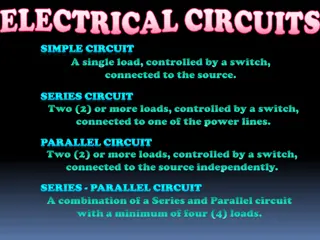
Series and parallel circuits
In a
series circuit
the total
voltage (PD) of the
supply
is
shared
between the various
components
, so the
voltages
around a series circuit
always
add up
to equal the
source
voltage.
Measuring voltage (PD) in a circuit.
Voltage is
measured
using a
VOLTMETER
Series and parallel circuits
In a
series circuit
the total
voltage (PD) of the
supply
is
shared
between the various
components
, so the
voltages
around a series circuit
always
add up
to equal the
source
voltage.
In a
parallel
circuit
all
components get
the
full source
voltage
, so the
voltage is the
same across all
components
Whenever a current flows
around an electrical circuit
there is
resistance
to the
electrons.
Whenever a current flows
around an electrical circuit
there is
resistance
to the
electrons.
Whenever a current flows
around an electrical circuit
there is
resistance
to the
electrons.
Resistance is calculated using this
equation:
resistance =
voltage
R =
V
current I
The unit of resistance is the ohm
Ω
(Greek letter omega)
Whenever a current flows
around an electrical circuit
there is
resistance
to the
electrons.
Resistance is calculated using this
equation:
resistance =
voltage
R =
V
current I
The unit of resistance is the ohm
Ω
(Greek letter omega)
eg. If a PD of 8V is needed to make a
current of 4A flow through a wire.
Resistance = 8 / 4 = 2
Ω
Remember, remember ……….. The equation
linking V, I and R
V
I
R
V = I x R
I = V / R
R = V / I
For metal conductors, resistance
increases with temperature. For
semi-conductors, it decreases
with temperature.
For metal conductors, resistance
increases with temperature. For
semi-conductors, it decreases
with temperature.
When a
current
flows through a wire,
resistance
causes a
heating effect
.
This principle is used in
heating
elements
and in
filament light bulbs
.
For metal conductors, resistance
increases with temperature. For
semi-conductors, it decreases
with temperature.
When a
current
flows through a wire,
resistance
causes a
heating effect
.
This principle is used in
heating
elements
and in
filament light bulbs
.
Electrons
collide
with
atoms as they pass
through
conductors
,
losing energy. The atoms
vibrate more
, causing a
heating effect
A
B
Wires A and B have the
same
cross-
sectional area and are at the same
temperature. Wire B is
twice
as
long
as wire A, and has
twice
the
resistance
.
A
B
Wires A and B have the
same
cross-
sectional area and are at the same
temperature. Wire B is
twice
as
long
as wire A, and has
twice
the
resistance
.
Resistance length
Resistance is
directly proportional
to length
A
B
Wires A and B have the
same
length
and are at the same temperature.
Wire B is
twice
the cross-sectional
area of A, and has
half
the
resistance
.
A
B
Wires A and B have the
same
length
and are at the same temperature.
Wire B is
twice
the cross-sectional
area of A, and has
half
the
resistance
.
Resistance
1
area
(area = cross-sectional area)
Some wires have
much more
resistance for a given length. For
example a 10cm length of
nichrome
has a
much higher resistance
than
copper
of the same length and
cross-sectional area.
Nichrome
is
said to have a
higher resistivity
.
Some wires have
much more
resistance for a given length. For
example a 10cm length of
nichrome
has a
much higher resistance
than
copper
of the same length and
cross-sectional area.
Nichrome
is
said to have a
higher resistivity
.
The Greek letter
rho
(
ρ
) is the
resistivity constant
for any given
material
)
Combining the resistance equations
Combining the resistance equations
Resistance
length
area
Combining the resistance equations
Resistance
length
area
R =
ρ
x
l
A
Combining the resistance equations
Resistance
length
area
R =
ρ
x
l
A
ρ
=
R x A
l
Combining the resistance equations
R =
ρ
x
l
A
ρ
=
R x A
l
Comparing different wires, A and B, made from the
same material (so
ρ
is the same for each wire)
at the same temperature.
Combining the resistance equations
Resistance
A
x Area
A
=
Resistance
B
x Area
B
Length
A
Length
B
R =
ρ
x
l
A
ρ
=
R x A
l
Comparing different wires, A and B, made from the
same material (so
ρ
is the same for each wire)
at the same temperature.
More about resistors
More about resistors
More about resistors
More about resistors
More about resistors
Ohm’s Law
A 19
th
Century scientist
who first investigated
the electrical
properties of wires, and
the relationship
between V, I and R
I (the symbol for current) = “intensite du courant”
Ohm’s Law
How current
varies with voltage
(PD) for a metal
conductor.
Circuit diagram:
A
V
battery
Variable
resistor
Ammeter
Voltmeter
Nichrome
wire
Water bath
to keep
nichrome at
constant
temperature
Ohm’s Law
How current
varies with voltage
(PD) for a metal
conductor.
Circuit diagram:
A
V
battery
Variable
resistor
Ammeter
Voltmeter
Nichrome
wire
Water bath
to keep
nichrome at
constant
temperature
Ohm’s Law
How current
varies with voltage
(PD) for a metal
conductor.
Circuit diagram:
A
V
battery
Variable
resistor
Ammeter
Voltmeter
Nichrome
wire
Water bath
to keep
nichrome at
constant
temperature
Current
(A)
Voltage (V)
0
2.0
10.0
Ohm’s Law
1.
A graph of current against
voltage is a straight line
through the origin.
2.
If the voltage doubles then
the current doubles, etc
3.
In this experiment, V/I
always has the same value.
Ohm’s Law
1.
A graph of current against
voltage is a straight line
through the origin.
2.
If the voltage doubles then
the current doubles, etc
3.
In this experiment, V/I
always has the same value.
Current is proportional to the voltage.
Current Voltage
Ohm’s Law
1.
A graph of current against
voltage is a straight line
through the origin.
2.
If the voltage doubles then
the current doubles, etc
3.
In this experiment, V/I
always has the same value.
Current is proportional to the voltage.
Current Voltage
Provided temperature is
constant
So what happens if
temperature changes?
For a
tungsten
filament lamp
,
as the current
increases, the
temperature
rises
and the
resistance
increases.
Current is
not
directly
proportional to
the voltage.
So what happens if
temperature changes?
For a
tungsten
filament lamp
,
as the current
increases, the
temperature
rises
and the
resistance
increases.
Current is
not
directly
proportional to
the voltage.
And for the diode …….
Current is
not
proportional
to the
voltage. If the voltage
is
reversed
, the
resistance
increases
greatly
, so effectively
making sure that
current
only flows in
one direction
in the
circuit.
And finally …
•
Understand that electric
circuits transfer energy
from the battery or power
source to the circuit
components then into the
surroundings
And finally …
•
Understand that electric
circuits transfer energy
from the battery or power
source to the circuit
components then into the
surroundings
Chemical energy
is
transformed into
potential
energy
in the electrons, and
in the bulb this is changed
into
thermal (heat) energy
.
And finally …
•
Understand that electric
circuits transfer energy
from the battery or power
source to the circuit
components then into the
surroundings
Chemical energy
is
transformed into
potential
energy
in the electrons, and
in the bulb this is changed
into
thermal (heat) energy
.
The
rate
at which
energy is
transformed
is known as
POWER
. The unit of power
is the
watt (W)
.
P = I x V
V = P / I
I = P / V
1 kilowatt (kW) = 1000 watts
And finally …
•
Understand that electric
circuits transfer energy
from the battery or power
source to the circuit
components then into the
surroundings
2200W (2.2kW)
450W
80W
11W
And finally …
Recall and use
the equations P
= IV and E = IVt
Supplement
And finally …
Recall and use
the equations P
= IV and E = IVt
Power =
energy transformed
time taken
Supplement
And finally …
Recall and use
the equations P
= IV and E = IVt
Power =
energy transformed
time taken
P =
E
t
Supplement
And finally …
Recall and use
the equations P
= IV and E = IVt
Power =
energy transformed
time taken
P =
E
t
E = P x t
Supplement
And finally …
Recall and use
the equations P
= IV and E = IVt
Power =
energy transformed
time taken
P =
E
t
E = P x t
E = I x V x t
Supplement
And finally …
Recall and use
the equations P
= IV and E = IVt
Power =
energy transformed
time taken
P =
E
t
E = P x t
E = I x V x t
Supplement
Joules per second
LEARNING
OBJECTIVES
PHYSICS – Electrical quantities (2)
Explore the concepts of electrical quantities such as e.m.f., potential difference, resistance, current, and voltage in circuits. Learn about using voltmeters, measuring resistance, transferring energy in circuits, and understanding the relationships between these electrical properties. Delve into experiments, equations, and characteristics of components like ohmic resistors and filament lamps.

Download Presentation

Please find below an Image/Link to download the presentation.
The content on the website is provided AS IS for your information and personal use only. It may not be sold, licensed, or shared on other websites without obtaining consent from the author. Download presentation by click this link. If you encounter any issues during the download, it is possible that the publisher has removed the file from their server.
E N D
Presentation Transcript
LEARNING OBJECTIVES Core State that the e.m.f. of an electrical source of energy is measured in volts State that the potential difference (p.d.) across a circuit component is measured in volts Use and describe the use of a voltmeter, both analogue and digital State that resistance = p.d. / current and understand qualitatively how changes in p.d. or resistance affect current Recall and use the equation R = V / I Describe an experiment to determine resistance using a voltmeter and an ammeter Relate (without calculation) the resistance of a wire to its length and to its diameter Understand that electric circuits transfer energy from the battery or power source to the circuit components then into the surroundings Supplement Show understanding that e.m.f. is defined in terms of energy supplied by a source in driving charge round a complete circuit Recall that 1 V is equivalent to 1 J / C Sketch and explain the current-voltage characteristic of an ohmic resistor and a filament lamp Recall and use quantitatively the proportionality between resistance and length, and the inverse proportionality between resistance and cross-sectional area of a wire Recall and use the equations P = IV and E = IVt
Recap Current is the rate of flow of electrons around a circuit. The higher the current, the faster the electrons are travelling. The unit of current is the amp, and in a circuit an ammeter is used to measure current. emf
Recap Current is the rate of flow of electrons around a circuit. The higher the current, the faster the electrons are travelling. The unit of current is the amp, and in a circuit an ammeter is used to measure current. emf VOLTAGE is the amount of energy given to electrons as they travel around the circuit.
Recap Current is the rate of flow of electrons around a circuit. The higher the current, the faster the electrons are travelling. The unit of current is the amp, and in a circuit an ammeter is used to measure current. emf VOLTAGE is the amount of energy given to electrons as they travel around the circuit. Voltage is also known as POTENTIAL DIFERENCE (PD)
Recap Current is the rate of flow of electrons around a circuit. The higher the current, the faster the electrons are travelling. The unit of current is the amp, and in a circuit an ammeter is used to measure current. emf VOLTAGE is the amount of energy given to electrons as they travel around the circuit. Unit of voltage or PD is the volt. Supplement 1 volt = 1 joule of potential energy is given to each coulomb of charge (1J = 1 J/C) Voltage is also known as POTENTIAL DIFERENCE (PD)
VOLTAGE is the amount of energy given to electrons as they travel around the circuit. emf Voltage is also known as POTENTIAL DIFERENCE (PD) The cell produces its highest potential difference when not connected in a circuit. This maximum PD is known as the electromotive force (EMF) of the cell. The battery cell gives electrons potential energy. This energy is then passed on to the components in the cell
VOLTAGE is the amount of energy given to electrons as they travel around the circuit. emf Voltage is also known as POTENTIAL DIFERENCE (PD) The cell produces its highest potential difference when not connected in a circuit. This maximum PD is known as the electromotive force (EMF) of the cell. As soon as the cell is connected in a circuit the potential difference drops because of energy wastage inside the cell. The battery cell gives electrons potential energy. This energy is then passed on to the components in the cell
VOLTAGE is the amount of energy given to electrons as they travel around the circuit. Just a reminder A single cell Voltage is also known as POTENTIAL DIFERENCE (PD) A battery, made up of several cells. A battery is a series of joined cells, although it is commonly used for a single cell as well. The cell produces its highest potential difference when not connected in a circuit. This maximum PD is known as the electromotive force (EMF) of the cell. As soon as the cell is connected in a circuit the potential difference drops because of energy wastage inside the cell. The battery cell gives electrons potential energy. This energy is then passed on to the components in the cell
Voltage is measured using a VOLTMETER Measuring voltage (PD) in a circuit.
Voltage is measured using a VOLTMETER Measuring voltage (PD) in a circuit. To measure the voltage across a component in a circuit the voltmeter must be placed in parallel with it.
Voltage is measured using a VOLTMETER Measuring voltage (PD) in a circuit. To measure the voltage across a component in a circuit the voltmeter must be placed in parallel with it.
Voltage is measured using a VOLTMETER Measuring voltage (PD) in a circuit. Series and parallel circuits In a series circuit the total voltage (PD) of the supply is shared between the various components, so the voltages around a series circuit always add up to equal the source voltage.
Voltage is measured using a VOLTMETER Measuring voltage (PD) in a circuit. Series and parallel circuits In a parallel circuit all components get the full source voltage, so the voltage is the same across all components In a series circuit the total voltage (PD) of the supply is shared between the various components, so the voltages around a series circuit always add up to equal the source voltage.
Whenever a current flows around an electrical circuit there is resistance to the electrons.
Whenever a current flows around an electrical circuit there is resistance to the electrons. Copper connecting wire is a good conductor, it offers little resistance to the electrons, and a current passes through it easily. Nichrome is not such a good conductor, it has a bigger resistance to the electrons, and less current will flow.
Whenever a current flows around an electrical circuit there is resistance to the electrons. Resistance is calculated using this equation: resistance = voltage current I R = V Copper connecting wire is a good conductor, it offers little resistance to the electrons, and a current passes through it easily. Nichrome is not such a good conductor, it has a bigger resistance to the electrons, and less current will flow. The unit of resistance is the ohm (Greek letter omega)
Whenever a current flows around an electrical circuit there is resistance to the electrons. Resistance is calculated using this equation: resistance = voltage current I R = V Copper connecting wire is a good conductor, it offers little resistance to the electrons, and a current passes through it easily. Nichrome is not such a good conductor, it has a bigger resistance to the electrons, and less current will flow. The unit of resistance is the ohm (Greek letter omega) eg. If a PD of 8V is needed to make a current of 4A flow through a wire. Resistance = 8 / 4 = 2
Remember, remember .. The equation linking V, I and R V = I x R V I = V / R I R R = V / I
Factors affecting resistance.
Length of wire Factors affecting resistance. Factors affecting resistance Cross sectional area Temperature Material
Length of wire Factors affecting resistance. Factors affecting resistance Cross sectional area Temperature Material For metal conductors, resistance increases with temperature. For semi-conductors, it decreases with temperature.
Length of wire Factors affecting resistance. Factors affecting resistance Cross sectional area Temperature Material For metal conductors, resistance increases with temperature. For semi-conductors, it decreases with temperature. When a current flows through a wire, resistance causes a heating effect. This principle is used in heating elements and in filament light bulbs.
Length of wire Factors affecting resistance. Factors affecting resistance Cross sectional area Temperature Material Electrons collide with atoms as they pass through conductors, losing energy. The atoms vibrate more, causing a heating effect For metal conductors, resistance increases with temperature. For semi-conductors, it decreases with temperature. When a current flows through a wire, resistance causes a heating effect. This principle is used in heating elements and in filament light bulbs.
Temperature Factors affecting resistance. Factors affecting resistance Cross sectional area Length of wire Material Wires A and B have the same cross- sectional area and are at the same temperature. Wire B is twice as long as wire A, and has twice the resistance. A B
Temperature Factors affecting resistance. Factors affecting resistance Cross sectional area Length of wire Material Wires A and B have the same cross- sectional area and are at the same temperature. Wire B is twice as long as wire A, and has twice the resistance. A B Resistance length Resistance is directly proportional to length
Temperature Factors affecting resistance. Factors affecting resistance Cross sectional area Length of wire Material Wires A and B have the same length and are at the same temperature. Wire B is twice the cross-sectional area of A, and has half the resistance. A B
Temperature Factors affecting resistance. Factors affecting resistance Cross sectional area Length of wire Material Wires A and B have the same length and are at the same temperature. Wire B is twice the cross-sectional area of A, and has half the resistance. A B Resistance 1 area (area = cross-sectional area)
Temperature Factors affecting resistance. Factors affecting resistance Length of wire Material Cross sectional area Some wires have much more resistance for a given length. For example a 10cm length of nichrome has a much higher resistance than copper of the same length and cross-sectional area. Nichrome is said to have a higher resistivity.
Temperature Factors affecting resistance. Factors affecting resistance Length of wire Material Cross sectional area Some wires have much more resistance for a given length. For example a 10cm length of nichrome has a much higher resistance than copper of the same length and cross-sectional area. Nichrome is said to have a higher resistivity. Typical resistivity ( /m) 49 x 10-8 Constantan 44 x 10-8 Manganin 100 x 10-8 Nichrome 55 x 10-8 Tungsten The Greek letter rho ( ) is the resistivity constant for any given material)
Length of wire Factors affecting resistance. Factors affecting resistance Cross sectional area Temperature Material Combining the resistance equations
Length of wire Factors affecting resistance. Factors affecting resistance Cross sectional area Temperature Material Combining the resistance equations Resistance length area
Length of wire Factors affecting resistance. Factors affecting resistance Cross sectional area Temperature Material Combining the resistance equations R = x l A Resistance length area
Length of wire Factors affecting resistance. Factors affecting resistance Cross sectional area Temperature Material Combining the resistance equations R = x l A = R x A l Resistance length area
Length of wire Factors affecting resistance. Factors affecting resistance Cross sectional area Temperature Material Combining the resistance equations R = x l A Comparing different wires, A and B, made from the same material (so is the same for each wire) at the same temperature. = R x A l
Length of wire Factors affecting resistance. Factors affecting resistance Cross sectional area Temperature Material Combining the resistance equations R = x l A Comparing different wires, A and B, made from the same material (so is the same for each wire) at the same temperature. = R x A l ResistanceAx AreaA= ResistanceBx AreaB LengthA LengthB
More about resistors 1 kilohm (k ) = 1000 1 megohm (M ) = 1 000 000 Resistor
More about resistors 1 kilohm (k ) = 1000 1 megohm (M ) = 1 000 000 Resistor Variable resistor Used for varying current, for example in light dimmer switches
More about resistors 1 kilohm (k ) = 1000 1 megohm (M ) = 1 000 000 Resistor Variable resistor Used for varying current, for example in light dimmer switches High resistance when cold, but much lower resistance when hot. Eg. Digital thermometer Thermistor
More about resistors 1 kilohm (k ) = 1000 1 megohm (M ) = 1 000 000 Resistor Variable resistor Used for varying current, for example in light dimmer switches High resistance when cold, but much lower resistance when hot. Eg. Digital thermometer High resistance in the dark but a low resistance in the light. Eg. Controlling light switches Thermistor Light dependent resistor (LDR)
More about resistors 1 kilohm (k ) = 1000 1 megohm (M ) = 1 000 000 Resistor Variable resistor Used for varying current, for example in light dimmer switches High resistance when cold, but much lower resistance when hot. Eg. Digital thermometer High resistance in the dark but a low resistance in the light. Eg. Controlling light switches Extremely high resistance in one direction, but low in the other. Controls flow of current Thermistor Light dependent resistor (LDR) Diode
Ohms Law A 19th Century scientist who first investigated the electrical properties of wires, and the relationship between V, I and R I (the symbol for current) = intensite du courant
Ohms Law How current varies with voltage (PD) for a metal conductor. Circuit diagram: battery Variable resistor Ammeter A Voltmeter V Water bath to keep nichrome at constant temperature Nichrome wire
Ohms Law How current varies with voltage (PD) for a metal conductor. Circuit diagram: battery V I R = V/I 5.0 2.0V 0.4A 4.0 0.8 5.0 Variable resistor Ammeter 6.0 1.2 5.0 A Voltmeter 8.0 1.6 5.0 V 10.0 2.0 5.0 Water bath to keep nichrome at constant temperature Nichrome wire
Ohms Law How current varies with voltage (PD) for a metal conductor. Circuit diagram: battery V I R = V/I 5.0 2.0V 0.4A 4.0 0.8 5.0 Variable resistor Ammeter 6.0 1.2 5.0 A Voltmeter 8.0 1.6 5.0 V 10.0 2.0 5.0 2.0 Current (A) Water bath to keep nichrome at constant temperature Nichrome wire 0 10.0 Voltage (V)
Ohms Law 1. A graph of current against voltage is a straight line through the origin. 2. If the voltage doubles then the current doubles, etc 3. In this experiment, V/I always has the same value.
Ohms Law 1. A graph of current against voltage is a straight line through the origin. 2. If the voltage doubles then the current doubles, etc 3. In this experiment, V/I always has the same value. Current is proportional to the voltage. Current Voltage
Ohms Law Provided temperature is constant 1. A graph of current against voltage is a straight line through the origin. 2. If the voltage doubles then the current doubles, etc 3. In this experiment, V/I always has the same value. Current is proportional to the voltage. Current Voltage
temperature changes? So what happens if For a tungsten filament lamp, as the current increases, the temperature rises and the resistance increases. Current is not directly proportional to the voltage.
")


 in a circuit.")