Understanding D'Arsonval Meter in Alternating Current Circuits
Explore the principles behind D'Arsonval meter in AC circuits, including half-wave rectification. Learn about sensitivity differences between DC and AC voltmeters, calculating series resistance, multiplier resistor values, and practical applications. Discover how shunt resistors improve linearity in half-wave rectification circuits.

Download Presentation

Please find below an Image/Link to download the presentation.
The content on the website is provided AS IS for your information and personal use only. It may not be sold, licensed, or shared on other websites without obtaining consent from the author. Download presentation by click this link. If you encounter any issues during the download, it is possible that the publisher has removed the file from their server.
E N D
Presentation Transcript
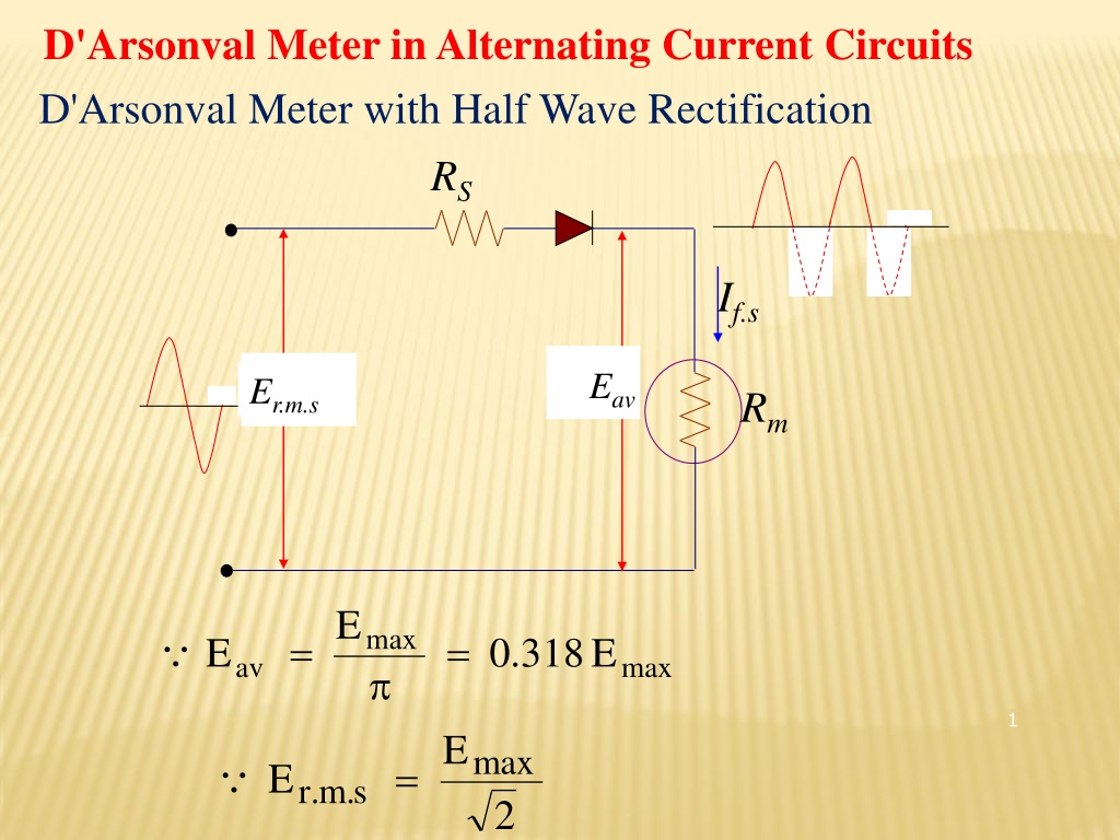
D'Arsonval Meter in Alternating Current Circuits D'Arsonval Meter with Half Wave Rectification RS If.s Eav Er.m.s Rm E max = = E . 0 318 E av max 1 E max = E . r m s . 2
= E . 1 414 E max . r m s . = . 1 = E . 0 318 414 E . 0 45 E av . r m s . . r m s . E av 45 = = E . 2 22 E . r m s . av . 0 The constant 2.22 is called the form factor The series resistance Rs can be calculated as E . 0 45 E c . d . r m s . = + = = R R R T S m c . d I c . d I E . 0 45 E c . d . r m s . = = R R R S m m 2 c . d I c . d I
Therefore, the pointer will deflect for a full scale if 10 Vdc is applied and only 4.5 V when a 10 Vrms sinusoidal signal is applied. The DC voltmeter sensitivity is given by: 1 = 1 = = 1 / S k V dc mA 1 I m For the circuit of the AC voltmeter sensitivity is given by: = = . 0 45 . 0 45 / S S k V ac dc This means that an AC voltmeter is not as sensitive as a DC voltmeter. 3
The total resistance RT can be calculated as E c . d = = R c . d S E T c . d c . d I where 1 = c . d S s . f I . 0 45 E = = = . . r m s . 0 45 R S E S E . . . . . . T d c r m s a c r m s I . d c + = = = R R R c . d S E c . a S E T S m c . d . r m s . 4
EXAMPLE Calculate the value of the multiplier resistor for a 10 Vrms range on the voltmeter shown in in the following Fig. RS = Is . f 1 mA E Er.m.s =10V av =300 Rm Solution = = = = E E . 0 45 E . 0 45 10 5 . 4 V 5 av c . d . r m s .
1 = = = S 1000 / V 1 k / V c . d I fs = = = S . 0 45 S . 0 45 1 k / V . 0 45 k / V c . a c . d = + = = = R R R S E 1 k / V 5 . 4 V 5 . 4 k T S m c . d c . d or = + = = = R R R S E . 0 45 k / V 10 V 5 . 4 k T S m c . a . r m s . = = = RS 5 . 4 k 300 5 . 4 k 3 . 0 k 2 . 4 k The series resistance Rs can also be calculated as . 0 45 E . 0 45 10 3 . r m s . = = = = R R 300 4200 2 . 4 k S m I 1 10 c . d 6
D1 RS Ein D2 R Rm Half wave rectification using an instrument rectifier and shunt resistor for improved linearity D2 is forward in the negative half-cycle and it is used to provide an alternate path for reverse biased leakage current Rsh is used to increase the current flow through D1 during the positive half cycle 7
D'Arsonval Meter with Full Wave Rectification The full-wave rectifier provide higher sensitivity rating compare to the half-wave rectifier. Bridge type rectifier is the most commonly used 8 Full Wave Bridge Rectifier Used in AC Voltmeter Circuit.
Operation; (a) During the positive half cycle (red arrow), currents flows through diode D2, through the meter movement from positive to negative, and through diode D3. - The polarities in circles on the transformer secondary are for the positive half cycle. - Since current flows through the meter movement on both half cycles, we can expect the deflection of the pointer to be greater than with the half wave cycle. - If the deflection remains the same, the instrument using full wave rectification will have a greater sensitivity. (b) Vise-versa for the negative half cycle (blue arrow). 9
From the circuit in Figure 5.9, the peak value of the 10 Vrms signal with the half-wave rectifier is, E . 1 = = 414 * 14 14 . E V p rms peak The average dc value of the pulsating sine wave is, = = . 0 636 9 E E V ave p Or can be compute as, = = = 9 . 0 * 9 . 0 * 10 9 E E V V ave rms The AC voltmeter using full-wave rectification has a sensitivity equal to 90% of the dc sensitivity or twice the sensitivity using half-wave rectification. 10 = 9 . 0 * S S ac dc
Example. Each diode in the full-wave rectifier circuit has an average forward bias resistance of 50 Ohm and is assumed to have an infinite resistance in the reverse direction. Calculate, (a) The multiplier Rs. (b) The AC sensitivity. (C)The equivalent DC sensitivity. 11 . AC Voltmeter Using Full-Wave Rectification and Shunt.
Solution: (a) Calculate the current shunt and total current, E I sh mA 1 * 500 = = = m mA 1 sh 500 R and = + = + = mA 1 mA 1 2 I I I mA T sh m The equivalent DC voltage is, = = = 9 . 0 * 10 9 . 0 * 10 0 . 9 E V V V dc rms E 0 . 9 V = = = dc 5 . 4 R K T 2 I mA T R R = m sh 2 R R R s T d + R R m sh 12 500 * 500 = = 4500 2 * 50 . 4 15 K + 500 500
(b) The ac sensitivity, R 4500 = = = T 450 / S V ac 10 Range V (c.) The dc sensitivity, 1 1 = = = 500 / S V dc 2 I mA T or S 9 . 0 450 / V = = = ac 500 / S V dc 9 . 0 13


 The ac sensitivity,")