Overview of Single-Cycle Implementation in Computer Organization
Today's lecture discussed the single-cycle implementation of processors, focusing on executing instructions in hardware based on the ISA. The process involves different cycles such as instruction fetch, decode, execution, memory access, and write-back. The presentation highlighted the functions of a simple MIPS processor supporting memory-related, arithmetic/logic, and control/transfer instructions. It also touched upon multi-cycle implementation and pipelining for faster operation.

Download Presentation

Please find below an Image/Link to download the presentation.
The content on the website is provided AS IS for your information and personal use only. It may not be sold, licensed, or shared on other websites without obtaining consent from the author. Download presentation by click this link. If you encounter any issues during the download, it is possible that the publisher has removed the file from their server.
E N D
Presentation Transcript
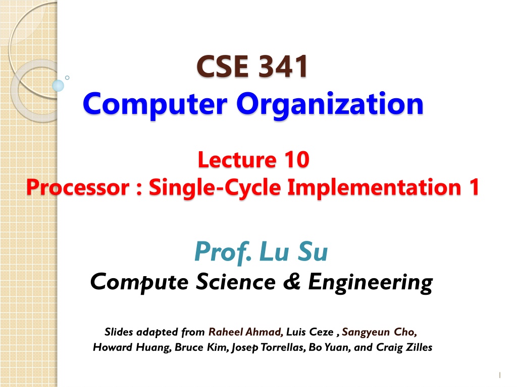
CSE 341 Computer Organization Lecture 10 Processor : Single-Cycle Implementation 1 Prof. Lu Su Compute Science & Engineering Slides adapted from Raheel Ahmad, Luis Ceze , Sangyeun Cho, Howard Huang, Bruce Kim, JosepTorrellas, Bo Yuan, and Craig Zilles 1
Todays Content in Big Picture SW Part-I Ch2 Part-II Ch3,4 Part-III Ch1,5,6 ch2 ch1 I/O device Ch6 Ch3,4 Ch5 Computer Organization and Design (5thedition) by Patterson and Hennessy 2
Goal of this Part Implement hardware to execute instructions -- ISA defines the hardware operations which are available to software. -- Instruction set can be implemented in different ways. 3
RISC Instruction Execution Instruction fetch cycle (IF) Send the program counter (PC) to memory Fetch the instruction from memory Update the next sequential PC Instruction decode/register fetch cycle (ID) Decode the instruction Read the registers corresponding to register source specifiers Execution/effective address cycle (EX) Memory reference (calculate effective address) Register-register ALU instruction Register-immediate ALU instruction Memory access (MEM) Load/store Write-back cycle (WB) 4
Outline of this Part Single-cycle implementation: --All operations takes in one clock cycle Multi-cycle implementation: -- Fast operations take less time than slower ones Pipelining -- Overlap the execution of several instructions 5
Task I Single-cycle implementation: --All operations takes in one clock cycle Multi-cycle implementation: -- Fast operations take less time than slower ones Pipelining -- Overlap the execution of several instructions 6
Functions of Simple Processor A simple MIPS processor can support a small instruction set: -- Memory-related instructions lw (load word) and sw (store word) --Arithmetic/logic instructions add, sub, and, or, slt,etc. -- Control/transfer instructions beq (branch if equal) j (unconditional jump) 7
Generic Implementation The CPU is in an infinite loop, fetching instructions from memory, decode them, and executing them. 8
Fetching Instruction Instructions are stored in Instructions Memory(IM) --Assume IM cannot be written or changed during running. Program Counter (PC) register holds the address of current instruction. -- MIPS instructions are 32 bits (4bytes) -- MIPS memory is byte addressable -- PC should be incremented by 32/8=4 Add 4 PC Read address Instruction [31-0] Instruction memory 9
Byte-addressable Memory Memory is byte-addressable. A 32-bit word occupies four contiguous locations (bytes) of memory The data output of instruction memory is still 32. Read address Instruction [31-0] Instruction memory 10
Decode Some fields of instructions (binary form) are the number of registers and the address of memory. -- rs -- rt -- rd -- address Other fields are used to generate the control signals. (We will discuss control unit later). -- op -- func 11
Review of R-type Instruction Register-to-register instructions: -- op: opcode -- func: specifies a particular arithmetic operation -- rs, rt and rd: source and destination registers -- shamt: shift op rs rt rd shamt 5 bits func 6 bits 6 bits 5 bits 5 bits 5 bits 12
Register File for R-type R-type instructions need to access registers and an arithmetic logic unit (ALU). MIPS register file stores 32 32-bit values. -- Each register specifier is 5 bits long. --Two registers can be read at a time. -- RegWrite is 1 to write register. RegWrite Read register 1 Read data 1 Read register 2 Read data 2 Write register Registers Write data 13
Boolean Algebra In Boolean algebra, all the variables have the values 0 or 1 and, in typical formulations, there are three operators: The OR operator is written as +, as in A + B. The OR operation is also called a logical sum, since its result is 1 if either operand is 1. The AND operator is written as , as in A B. The AND operator is also called logical product, since its result is 1 only if both operands are 1. The unary operator NOT is written as . Applying the operator NOT to a logical value results in an inversion or negation of the value (i.e., if the input is 0 the output is 1, and vice versa). 14
Boolean Algebra Laws of Boolean algebra 15
Truth Tables A combinational logic block contains no memory can be completely specified by defining the values of the outputs for each possible set of input values. Such a description is normally given as a truth table. For a logic block with n inputs, there are 2nentries in the truth table. Example: D is true if at least one input is true, E is true if exactly two inputs are true, and F is true only if all three inputs are true. 16
Logic Equations Show the logic equations for the logic functions, D, E, and F, described in the previous example. Think of E in two parts: what must be true for E to be true (two of the three inputs must be true), and what cannot be true (all three cannot be true). Thus we can write E as: E is true only if exactly two of the inputs are true. Then we can also write E as an OR of the three possible terms that have two true inputs and one false input: 17
Gate 18
Combinational Logic Decoders: n-bit input, 2noutputs, where only one output is asserted for each input combination. 19
Multiplexors (Selector) Inputs: data values and selector (or control) values. Output: one of the inputs that is selected by a control. 20
Arithmetic Logic Unit (ALU) The device that performs the arithmetic operations like addition and subtraction or logical operations like AND and OR. This section constructs an ALU from four hardware building blocks (AND and OR gates, inverters, and multiplexors) and illustrates how combinational logic works. 21
A 1-Bit ALU 22
Addition An adder must have two inputs for the operands and a single-bit output for the sum. There must be a second output to pass on the carry, called CarryOut. Since the CarryOut from the neighbor adder must be included as an input, we need a third input. This input is called CarryIn. 23
Addition 24


")
")