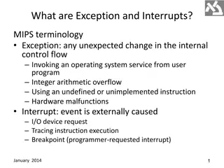
MIPS Single-cycle Datapath Analysis for Instruction SW

Examine the operation of the single-cycle datapath for a specific MIPS instruction "SW.R4,-100(R16)". This analysis covers the instruction word value, register numbers, control signals, and the logic diagram implementation. Dive into details like instruction word encoding, register file operations, and control signal values for a deeper understanding.

Download Presentation

Please find below an Image/Link to download the presentation.
The content on the website is provided AS IS for your information and personal use only. It may not be sold, licensed, or shared on other websites without obtaining consent from the author. Download presentation by click this link. If you encounter any issues during the download, it is possible that the publisher has removed the file from their server.
E N D
Presentation Transcript
SOLUTIONS CHAPTER 4
EXERCISE 4.9 In this exercise we examine the operation of the single-cycle datapath for a particular instruction. Problems in this exercise refer to the following MIPS instruction: Instruction SW R4, -100(R16) SLT R1, R2, R3 a b
4.9.1 What is the value of the instruction word? Solution: Binary Hexadecimal AA040064 0043082A a b 101011 10000 00100 0000000001100100 000000 00010 00011 00001 00000 101010
4.9.2 What is the register number supplied to the register file s read register 1 input? Is this register actually read? How about read register 2 ? Solution: Read Register 1 16 (10000b) 2 (00010b) Actually Read? Read Register Actually Read? 2 a b Yes Yes 4 (00100b) 3 (00011b) Yes Yes
4.9.3 What is the register number supplied to the register file s write register input? Is this register actually written? Solution: Read Register 1 Register Actually Written? a Either 4 (00100b) or 0 (don t know because RegDst is X) 1 (00001b) No b Yes
Different instructions require different control signals to be asserted in the datapath. The remaining problems in this exercise refer to the following two control signals from Figure 4.24. Control signal 1 ALUSrc Jump Control signal 2 Branch RegDst a b
4.9.4 What is the value of these two signals for this instruction? Solution: Control signal 1 ALUSrc=1 Jump=0 Control signal 2 Branch=0 RegDst=1 a b
4.9.5 For the datapath from figure 4.24, draw the logic diagram for the part of the control unit that implements just the first signal. Assure that we only need to support LW, SW, BEQ, ADD, and J(jump) instructions. Solution: We use I31 through I26 to denote individual bits of instruction[31:26], which is the input to the Control unit: ALUSrc = I31 Jump = (NOT I31) AND I27 a b
4.9.6 Repeat 4.9.5, but now implement both of these signals. Solution: If possible, we try to reuse some or all of the logic needed for one signal to help us compute the other signal at a lower cost: ALUSrc = I31 Branch = I28 RegDst = NOT I31 Jump = RegDst AND I27 a b
EXERCISE 4.10 In this exercise we examine how the clock cycle time of the processor affects the design of the control unit, and vice versa. Problems in this exercise assume that the logic blocks used to implement the datapath have the following latencies. I-Mem Add MUX ALU Regs D-Mem Sign- Shift- left-2 ALU Ctrl exten d 15ps a 200ps 70ps 20ps 90ps 90ps 250ps 10ps 30ps b 750ps 200ps 50ps 250ps 300ps 500ps 100ps 5ps 70ps To solve the problems in this exercise, it helps to first determine the latencies of different paths inside the processor. Assuming zero latency for the Control unit, the critical path is the path to get the data for a load instruction, so we have I-Mem,Mux, Regs, Mux, ALU, D-Mem, and Mux on this path.
SINGLE CYCLE DATAPATH WITH CONTROL UNIT 0 Add 1 Add 4 Shift left 2 PCSrc ALUOp Branch MemRead Control Unit MemtoReg Instr[31-26] MemWrite ALUSrc RegWrite RegDst ovf Instr[25-21] Read Addr 1 Instruction Memory Read Data 1 Address Register Instr[20-16] zero Read Addr 2 Data Memory File Read Address 0 1 PC Instr[31-0] Read Data ALU Write Addr 0 Read Data 2 1 0 Write Data Instr[15 -11] Write Data 1 Sign Extend Instr[15-0] ALU control 16 32 Instr[5-0]
4.10.1 To avoid lengthening the critical path of the datapath shown in Figure 4.24, how much time can the control unit take to generate the MemWrite signal? Solution: The Control unit can begin generating MemWrite only after I- Mem is read. It must finish generating this signal before the end of the clock cycle. Note that MemWrite is actually a write- enable signal for D-Mem flip-flops, and the actual write is triggered by the edge of the clock signal, so MemWrite need not arrive before that time. So the Control unit must generate the MemWrite in one clock cycle, minus the I-Mem access time: Critical Path Maximum Time to Generate MemWrite 690ps 200ps = 490ps a 200ps + 20ps + 90ps + 20ps + 90ps + 250ps + 20ps = 690ps 750ps + 50ps + 300ps + 50ps + 250ps + 500ps + 50ps = 1950ps b 1950ps 750ps = 1200ps
4.10.2 Which control signal in Figure 4.24 has the most slack and how much time does the control unit have to generate if it wants to avoid being on the critical path? Solution: All control signals start to be generated after I-Mem read is complete. The most slack a signal can have is until the end of the cycle, and MemWrite and RegWrite are both needed only at the end of the cycle, so they have the most slack. The time to generate both signals without increasing the critical path is the one computed in 4.10.1.
TIME DELAY FOR LW: CRITICAL PATH Clk PC+4 PC Clk-to-Q New Value Old Value PC+4 PC Instruction Memory Access Time New Value Rs, Rt, Rd, Op, Func Old Value Delay through Control Logic ALUct r ExtOp Old Value New Value Old Value New Value ALUSrc Old Value New Value MemtoReg Old Value New Value Register Write Occurs RegWr Old Value New Value Register File Access Time busA Old Value New Value Delay through Extender & Mux busB Old Value New Value ALU Delay Addres s Old Value New Value Data Memory Access Time busW New Old Value
4.10.3 Which control signal in Figure 4.24 is the most critical to generate quickly and how much time does the control unit have to generate it if it wants to avoid being on the critical path? Solution: MemWrite and RegWrite are only needed by the end of the cycle. RegDst, Jump, and MemtoReg are needed one Mux latency before the end of the cycle, so they are more critical than MemWrite and RegWrite. Branch is needed two Mux latencies before the end of the cycle, so it is more critical than these. MemRead is needed one D- Mem plus one Mux latency before the end of the cycle, and D-Mem has more latency than a Mux, so MemRead is more critical than Branch. I-Mem, Mux, Regs, Mux, ALU, D-Mem, and Mux
Solution: ALUOp must get to ALU control in time to allow one ALU Ctrl, one ALU, one D-Mem, and one Mux latency before the end of the cycle. This is clearly more critical than MemRead. Finally, ALUSrc must get to the pre-ALU Mux in time, one Mux, one ALU, one D-Mem, and one Mux latency before the end of the cycle. Again, this is more critical than MemRead. Between ALUOp and ALUSrc, ALUOp is more critical than ALUSrc if ALU control has more latency than a Mux. If ALUOp is the most critical, it must be generated one ALU Ctrl latency before the critical-path signals can go through Mux, Regs, and Mux. If the ALUSrc signal is the most critical, it must be generated while the critical path goes through Mux and Regs. The Most Critical Control Signal Is ALUOp (30ps > 20ps) ALUOp (70ps > 50ps) Time to Generate It without Affecting the Clock Cycle Time a b 20ps + 90ps + 20ps 30ps = 100ps 50ps + 300ps + 50ps 70ps = 330ps
The remaining problems in this exercise assume that the time needed by the control unit to generate individual control signals is as follows: RegDs t h Read Jump Branc Mem Memt o Reg ALUO p Mem Write ALUSr c Reg Write a 500ps 500ps 450ps 200ps 450ps 200ps 500ps 100ps 500ps b 1100ps For the next three problems, it helps to compute for each signal how much time we have to generate it before it starts affecting the critical path. We already did this for RegDst and RegWrite in 4.10.1, and in 4.10.3 we described how to do it for the remaining control signals. We have: 1000ps 1100ps 800ps 1200ps 300ps 1300ps 400ps 1200ps RegDs t Jump Branc h Mem Read Memt o Reg ALUO p Mem Write ALUSr c Reg Write a 470ps 470ps 450ps 220ps 470ps 100ps 490ps 110ps 490ps b 1150ps 1150ps 1100ps 650ps 1150ps 330ps 1200ps 350ps 1200ps
The difference between the allowed time and the actual time to generate the signal is called slack. For this problem, the allowed time will be the maximum time the signal can take without affecting clock cycle time. If slack is positive, the signal arrives before it is actually needed and it does not affect clock cycle time. If the slack is negative, the signal is late and the clock cycle time must be adjusted. We now compute the slack for each signal: RegDs t Jum p Branc h Mem Read Memt o Reg 20ps ALU Op Mem Write ALU Src Reg Writ e 10p s 0ps a 30ps 30p s 150ps 0ps 0ps 20ps 100p s 30ps 10ps 10ps b 50ps 150p s 50ps 100p s 50p s
4.10.4 What is the clock cycle time of the processor? Solution: The clock cycle time is what we computed in 4.10.1, plus the absolute value of the most negative slack. We have: Control Signal with the Most Negative Slack Is a ALUOp ( 100ps) 690ps b MemRead ( 150ps) 1950ps Clock Cycle Time with Ideal Control Unit (from 4.10.1) Actual Clock Cycle Time with These Signal Latencies 790ps 2100ps
4.10.5 If you can speed up the generation of control signals, but the cost of the entire processor increases by $1 for each 5ps improvement of a single control signal, which control signals would you speed up and by how much to maximize performance? What is the cost (per processor) of this performance improvement ? Solution: It only makes sense to pay to speed up signals with negative slack, because improvements to signals with positive slack cost us without improving performance. Furthermore, for each signal with negative slack, we need to speed it up only until we eliminate all its negative slack, so we have:
Solution: Signals with Negative Slack RegWrite ( 10ps) RegDst and Jump ( 30ps) ALUOp ( 100ps) MemtoReg and ALUSrc ( 50ps) MemWrite ( 100ps) MemRead ( 150ps) Per-Processor Cost to Eliminate All Negative Slack 170ps at $1/5ps = $34 a b 350ps at $1/5ps = $70
4.10.6 If the processor is already too expensive, instead of paying to speed it up as we did in 4.10.5, we want to minimize its cost without further slowing it down. If you can use slower logic to implement control signals, saving $1 of the processor cost for each 5ps you add to the latency of a single control signal, which control signals would you slow down and by how much to reduce the processor s cost without slowing it down?
Solution: The signal with the most negative slack determines the new clock cycle time. The new clock cycle time increases the slack of all signals until there is no remaining negative slack. To minimize cost, we can then slow down signals that end up having some (positive) slack. Overall, the cost is minimized by slowing signals down by: RegDs t h Read o Reg a 70ps 70ps 100ps 120ps 120ps Jump Branc Mem Memt ALUO p Mem Write ALUSr c Reg Write 0ps 90ps 110ps 90ps b 200ps 300ps 150ps 0ps 100ps 180ps 50ps 100ps 150ps
EXERCISE 4.11 In this exercise we examine in detail how an instruction is executed in a single-cycle datapath. Problems in this exercise refer to a clock cycle in which the processor fetches the following instruction word: Instruction word a b 101011 00011 00010 0000000000010100 000000 00100 00010 00001 00000 101010
4.11.1 What are the outputs of the sign-extend and the jump shift left 2 unit (near the top of Figure 4.24) for this instruction word? Solution: Sign-Extend Jump s Shift-Left-2 a 00000000000000000000000000010100 0001100010000000000001010000 b 00000000000000000000100000101010 0010000010000010000010101000
4.11.2 What are the values of the ALU control units inputs for this instruction? Solution: ALUOp[1-0] Instruction[5-0] a b 00 10 010100 101010
4.11.3 What is the new PC address after this instruction is executed? Highlight the path through which this value is determined. Solution: New PC PC + 4 PC + 4 Path a b PC to Add (PC + 4) to branch Mux to jump Mux to PC PC to Add (PC + 4) to branch Mux to jump Mux to PC
The remaining problems in this exercise assume that data memory is all zeros and that the processor s registers have the following values at the beginning of the cycle in which the above instruction word is fetched: R0 R1 R2 R3 R4 R5 R6 R8 R12 R31 a 0 -1 2 -3 -4 10 6 8 2 -16 b 0 256 -128 19 -32 13 -6 -1 16 -2
4.11.4 For each Mux, show the values of its data output during the execution of this instruction and these register values. Solution: WrReg Mux ALU Mux 20 Mem/ALU Mux X Branch Mux PC + 4 Jump Mux PC + 4 a 2 or 0 (RegDst is X) b 1 128 0 PC + 4 PC + 4
4.11.5 For the ALU and the two add units, what are their data input values? Solution: ALU 3 and 20 Add (PC + 4) PC and 4 Add (Branch) PC + 4 and 20 4 a b 32 and 128 PC and 4 PC + 4 and 2090 4
4.11.6 What are the values of all inputs for the Registers unit? Solution: Read Register 1 3 Read Register 2 2 Write Register X (2 or 0) Write Data X RegWrit e 0 a b 4 2 1 0 1
EXERCISE 4.12 In this exercise, we examine how pipelining affects the clock cycle time of the processor. Problems in this exercise assume that individual stages of the datapath have the following latencies: IF Id a 250ps 350ps 150ps b 200ps 170ps 220ps EX MEM 300ps 210ps WB 200ps 150ps
4.12.1 What is the clock cycle time in a pipelined and non- pipelined processor? Solution: Pipelined 350ps Single-Cycle 1250ps a b 1100ps 950ps
4.12.2 What is the total latency of an LW instruction in a pipelined and non-pipelined processor? Solution: Pipelined Single-Cycle a 1750ps 1250ps b 1100ps 950ps
4.12.3 If we can split one stage of the pipelined datapath into two new stages, each with half the latency of the original stage, which stage would you split and what is the new clock cycle time of the processor? Solution: Stage to Split New Clock Cycle Time 300ps 210ps a b ID EX
The remaining problems in this exercise assume that instructions executed by the processor are broken down as follows: ALU 45% 55% BEQ 20% 15% LW 20% 15% SW 15% 15% a b
4.12.4 Assuming there are no stalls or hazards, what is the utilization of the data memory? Solution: a.35% b.30%
4.12.5 Assuming there are no stalls or hazards, what is the utilization of the write-register port of the Register unit? Solution: a.65% b.70%
4.12.6 Instead of a single-cycle organization, we can use a multi-cycle organization where each instruction takes multiple cycles but one instruction finishes before another is fetched. In this organization, an instruction only goes through stages it actually needs (e.g., ST only takes 4 cycles because it does not need the WB stage). Compare clock cycle times and execution times with single-cycle, multi-cycle, and pipelined organization.
Solution: We already computed clock cycle times for pipelined and single- cycle organizations in 4.12.1, and the multi-cycle organization has the same clock cycle time as the pipelined organization. We will compute execution times relative to the pipelined organization. In single-cycle, every instruction takes one (long) clock cycle. In pipelined, a long-running program with no pipeline stalls completes one instruction in every cycle. Finally, a multi-cycle organization completes an LW in 5 cycles, an SW in 4 cycles (no WB), an ALU instruction in 4 cycles (no MEM), and a BEQ in 4 cycles (no WB). So we have the speedup of pipeline: Multi-Cycle Execution Time Is X Times Pipelined Execution Time, where X is 0.20 5 + 0.80 4 = 4.20 0.15 5 + 0.85 4 = 4.15 Single-Cycle Execution Time Is X Times Pipelined Execution Time, Where X Is 1250ps/350ps = 3.57 950ps/220ps = 4.32 a b
EXERCISE 4.13 In this exercise, we examine how data dependences affect execution in the basic 5-stage pipeline described in Section 4.5. Problems in this exercise refer to the following sequence of instructions: Instruction Sequence SW R16, -100(R6) LW R4, 8(R16) ADD R5, R4, R4 OR R1, R2, R3 OR R2, R1, R4 OR R1, R1, R2 a b
4.13.1 Indicate dependences and their type. Solution: Instruction Sequence I1: SW R16, 100(R6) I2: LW R4,8(R16) I3: ADD R5,R4,R4 I1: OR R1,R2,R3 I2: OR R2,R1,R4 I3: OR R1,R1,R2 Dependences RAW on R4 from I2 to I3 a b RAW on R1 from I1 to I2 and I3 RAW on R2 from I2 to I3 WAR on R2 from I1 to I2 WAR on R1 from I2 to I3 WAW on R1 from I1 to I3
4.13.2 Assume there is no forwarding in this pipelined processor. Indicate hazards and add NOP instructions to eliminate them. Solution: In the basic five-stage pipeline WAR and WAW dependences do not cause any hazards. Without forwarding, any RAW dependence between an instruction and the next two instructions (if register read happens in the second half of the clock cycle and the register write happens in the first half). The code that eliminates these hazards by inserting NOP instructions is:
Instruction Sequence a SW R16, 100(R6) LW R4,8(R16) NOP NOP ADD R5,R4,R4 b OR R1,R2,R3 NOP NOP OR R2,R1,R4 NOP NOP OR R1,R1,R2 Delay I3 to avoid RAW hazard on R4 from I2 Delay I2 to avoid RAW hazard on R1 from I1 Delay I3 to avoid RAW hazard on R2 from I2
4.13.3 Assume there is full forwarding. Indicate hazards and add NOP instructions to eliminate them. Solution: With full forwarding, an ALU instruction can forward a value to the EX stage of the next instruction without a hazard. However, a load cannot forward to the EX stage of the next instruction (but can to the instruction after that). The code that eliminates these hazards by inserting NOP instructions is: Instruction Sequence a SW R16, 100(R6) LW R4,8(R16) NOP ADD R5,R4,R4 Value for R4 is forwarded from I2 now b OR R1,R2,R3 OR R2,R1,R4 No RAW hazard on R1 from I1 (forwarded) Delay I3 to avoid RAW hazard on R4 from I2
Without Forwarding 250ps 180ps With Full Forwarding 300ps 240ps With ALU-ALU Forwarding Only 290ps 210ps a b
4.13.4 What is the total execution time of this instruction sequence without forwarding and with full forwarding? What is the speedup achieved by adding full forwarding to a pipeline that had no forwarding? Solution: The total execution time is the clock cycle time times the number of cycles. Without any stalls, a three-instruction sequence executes in 7 cycles (5 to complete the first instruction, then one per instruction). The execution without forwarding must add a stall for every NOP we had in 4.13.2, and execution forwarding must add a stall cycle for every NOP we had in 4.13.3. Overall, we get: No Forwarding With Forwarding Speedup Due to Forwarding 0.94 (really a slowdown) a (7 + 2) 250ps = 2250ps (7 + 1) 300ps = 2400ps b (7 + 4) 180ps = 1980ps 7 240ps = 1680ps 1.18