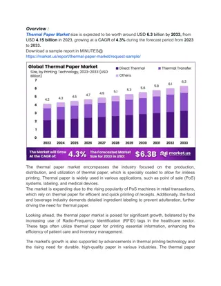
Fundamentals of Environmental Thermal Engineering in Mechanical & Aerospace Engineering

Explore the key concepts of environmental thermal engineering in Mechanical & Aerospace Engineering, covering topics such as the Carnot cycle, actual vapor-compression cycle, principles of the vapor-compression cycle, Carnot heat engine, refrigeration cycle, and coefficient of performance. Understand the processes behind the Carnot refrigeration cycle and the significance of the Carnot cycle as a benchmark for efficiency comparison.

Download Presentation

Please find below an Image/Link to download the presentation.
The content on the website is provided AS IS for your information and personal use only. It may not be sold, licensed, or shared on other websites without obtaining consent from the author. Download presentation by click this link. If you encounter any issues during the download, it is possible that the publisher has removed the file from their server.
E N D
Presentation Transcript
Environmental Thermal Engineering Lecture # 2 Min soo Kim Mechanical & Aerospace Engineering
Carnot cycle and Actual vapor-compression cycle
Fundamentals of cycle The vapor-compression cycle Most important refrigeration cycle (Most widely used cycle) Process 1. 2. 3. 4. Vapor compressed Condensed to a liquid Pressure is dropped Evaporate at a low pressure
Fundamentals of cycle Carnot heat engine and refrigeration cycle 2 3 3 2 Temperature, K Temperature, K 4 1 4 1 Entropy, kJ/kg K Entropy, kJ/kg K Carnot heat engine Refrigeration cycle
Fundamentals of cycle Schematic and T-S diagram of Carnot ref. cycle Condenser 3 2 3 2 Temperature, K Turbine 1 4 1 Compressor 4 Entropy, kJ/kg K Evaporator
Fundamentals of cycle Processes of the Carnot refrigeration cycle 1 - 2 Adiabatic compression 2 3 Isothermal rejection of heat 3 4 Adiabatic expansion 4 1 Isothermal addition of heat 3 2 Temperature, K 4 1 Entropy, kJ/kg K The reason why we discuss the Carnot cycle The Carnot cycle serves as a standard of comparison. The Carnot cycle provides a convenient guide to the temperatures that should be maintained to achieve maximum effectiveness
COP Coefficient of performance (1) The concept of the performance index of the refrigeration cycle is the same as efficiency. It represent the ratio Magnitude of desired commodity Magnitudeof expenditure
COP Coefficient of performance (2) The performance term in the refrigeration cycle is called the coefficient of performance (COP) , define as, useful refrigeration net work = COP
COP Condition for highest coefficient of performance Express the COP of the Carnot cycle in terms of the temperatures that exist in the cycle. We know the heat transferred in a reversible process can express T his way. = q Tds
T-S diagram analysis T-S diagram (1) 2 3 Temperature, K Net work 1 4 Refrigeration Entropy, kJ/kg K This Figure can represent the amount of useful refrigeration and the net work .
T-S diagram analysis T-S diagram (2) The useful refrigeration and net work ( ) T s s Useful refrigeration = 1 1 4 ( )( ) T T s s Net work = 2 1 1 4 Expression for COP of Carnot refrigeration cycle ( T ) T s s T = = 1 1 4 1 COP ( )( ) T s s T T 2 1 1 4 2 1
T-S diagram analysis How can we achieve a highest COP in Carnot cycle? T = 1 COP T T 2 1 1. A low value of T2will make the COP high 2. A high value of T1will make the COP high The value of T1has a more pronounced effect on the COP than T2, because a high value of T1increases the numerator and decreases the denominator.
T-S diagram analysis Temperature limitation Temperature, K 2 T 1T Entropy, kJ/kg K Can we have the infinite COP as T1is set equal to T2?
T-S diagram analysis Heat transfer 3 2 Temperature, K 4 1 Entropy, kJ/kg K In this heat rejection process, refrigerant must transfer its heat to somewhere. In this refrigeration process, refrigerant must add the heat from the cold room. 2 3 4 1
T-S diagram analysis Example 303.15 K Temperature, K 253.15 K Entropy, kJ/kg K If the refrigeration system must maintain a cold room at 20 and can reject heat to the atmosphere at 30 , how can we control the temperatures, T1and T2?
T-S diagram analysis The answer (1) 1T 303.15 K Temperature, K 253.15 K 2 T Entropy, kJ/kg K T1must be higher than 303.15K. T2must be lower than 253.15K.
T-S diagram analysis The answer (2) T 303.15 K Temperature, K 253.15 K T Entropy, kJ/kg K For higher COP, we can keep the T as small as possible.
Overall heat transfer Reduction of T q = heat, W U = overall heat-transfer coefficient, A = heat-transfer area, T = temperature change, K q UA T = Reduction of T can be accomplished by increasing A or U in equation.
Overall heat transfer How to accomplish high U ? In reality, we can make U high rather than make A high for given q, because we need to make less the space of refrigerator. But a large heat transfer area is accomplished
Overall heat transfer For a high value of U (1) 1. We can make the air speed around heat exchanger high. air
Overall heat transfer For a high value of U (2) 2. We can use the finned tube. Helically finned tube The low finned tube
Overall heat transfer For a high value of U (3) 3. The water around the heat exchanger will help the heat exchange. water (But it will promote to corrode the heat exchanger.)
Compression process 1 2 Temperature, K 2 3 4 1 Entropy, kJ/kg K
Compression process Two kinds of compression 1. 2. Wet compression compression with liquid droplet Dry compression compression with no droplet of liquid
Compression process Problem of wet compression 1. Liquid refrigerant may be trapped in the head of the cylinder by the rising piston, possibly damaging the valve or the cylinder head. 2. High-speed compressor are susceptible to damage by liquid because of the short time available for heat transfer. 3. The droplet of liquid may wash the lubricating oil from the walls of the cylinder, accelerating wear.
Revision of the Carnot cycle Dry compression Superheat horn 2 Temperature, K 3 1 4 Entropy, kJ/kg K If the refrigerant entering compressor is saturated vapor, the compression from point 1 to 2 is called dry compression.
Revision of the Carnot cycle Superheat horn Superheat horn 2 Temperature, K 3 1 4 Entropy, kJ/kg K On the temperature-entropy diagram superheat horn represent the additional work for dry compression.
Expansion process 3 4 Temperature, K 2 3 4 1 Entropy, kJ/kg K
Another revision in expansion process The practical difficulties in expansion engine (1) 1. The possible work that can be derived from the engine is a small fraction of that which must be supplied to the compressor. Practical difficulties such as lubrication intrude when a fluid of two phases drives the engine. The economics of the power recovery have in the past not justified the cost of the expansion engine. 2. 3.
Expansion process The practical difficulties in expansion engine (2) But using engine to energy cost increases. the possibility an should studied of expansion continue as be the
Expansion process Throttling device Because remains of reducing the pressure expansion process can use throttling device such as a valve. necessity still in the we Expansion valve
Expansion process Isenthalpic process Throttling expansion valve. No changes in potential and kinetic energy and with no heat loss, h3= h4; that is, the process is isenthalpic. The constant-enthalpy throttling process is irreversible, and during the process the entropy increases. happens in expansion device such as an
Expansion process Throttling process 2 Temperature, K 3 1 4 Entropy, kJ/kg K The throttling process take place 3 4 in this figure.
Standard vapor-compression cycle Compression process 2 1-2 process Reversible compression from saturated vapor to the condenser pressure Temperature, K 3 and adiabatic 1 4 Entropy, kJ/kg K
Standard vapor-compression cycle Condensation process 2 Temperature, K 2-3 process Reversible rejection heat at constant pressure, causing and condensation of the refrigerant. 3 1 de-superheating 4 Entropy, kJ/kg K
Standard vapor-compression cycle Expansion process 2 3-4 process Irreversible expansion at constant enthalpy from saturated liquid to the evaporator pressure Temperature, K 3 1 4 Entropy, kJ/kg K
Standard vapor-compression cycle Evaporation process 2 4-1 process Reversible constant evaporation to saturated vapor Temperature, K 3 addition pressure of heat causing at 1 4 Entropy, kJ/kg K
Standard vapor-compression cycle P - h diagram of refrigerant Critical point s = constant v = Pressure, kPa constant The pressure- enthalpy diagram is the usual graphic presenting refrigerant properties. t= constant means of Saturated- vapor line Saturated- liquid line Enthalpy, kJ/kg
Standard vapor-compression cycle The actual p-h diagram of R22
Standard vapor-compression cycle Cycle on the pressure-enthalpy diagram 3 2 Condensation Pressure, kPa In enthalpy important properties sought, and the pressure can determined most easily. refrigeration is practice, of the one the most Expansion Compression usually be 1 Evaporation 4 Enthalpy, kJ/kg
Standard vapor-compression cycle COP The work of compression = h2 h1 The refrigerating effect = h1 h4 3 2 Condensation Pressure, kPa Expansion Compression 1 Evaporation 4 h h h h = 1 4 COP 2 1 Enthalpy, kJ/kg 2h 1h 4h
Liquid line suction line heat exchange
Liquid line suction line heat exchange LLSL-HX Liquid line suction line heat exchange cycle Normal cycle
Liquid line suction line heat exchange Schematic and graph 2 3 Pressure, kPa 3 2 2 4 1 6 4 6 1 5 4 5 Enthalpy, kJ/kg
Liquid line suction line heat exchange Advantage 1. 2. 3. Superheating of the vapor leaving the evaporator Subcooling of the liquid leaving the condenser Increased the refrigeration effect = m h Q ( h = refrigeration effect )
Liquid line suction line heat exchange Disadvantage 1. Increase compressor work = ' w h h Pressure, kPa 2 6 3 2 2 4 = w h h 6 1 2 1 5 4 Enthalpy, kJ/kg 2. Additional cost of heat exchanger
Actual vapor-compression cycle Subcooling Pressure drop 3 2 Pressure ,kPa 1 4 Superheating Pressure drop Enthalpy, kJ/kg 1. 2. 3. 4. Pressure drop in the compressor and evaporator Superheating of the vapor leaving the evaporator Subcooling of the liquid leaving the condenser The compression is not isentropic. ( There are inefficiencies due to friction and other losses. )