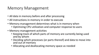
Understanding Computer Organization and Memory Management

Explore the fundamentals of computer organization, memory organization, and execution of instructions in a processor. Learn about memory addressing, word lengths, byte organization, and access methods. Understand the role of registers in the control path for instruction execution. Delve into MIPS language, memory organization, and the steps involved in processing instructions.

Download Presentation

Please find below an Image/Link to download the presentation.
The content on the website is provided AS IS for your information and personal use only. It may not be sold, licensed, or shared on other websites without obtaining consent from the author. Download presentation by click this link. If you encounter any issues during the download, it is possible that the publisher has removed the file from their server.
E N D
Presentation Transcript
Computer Organization 2015 - 2016 1
Instructions Language of The Computer (MIPS) 2
Memory organization Information is stored in the memory as a collection of bits. Collection of bits are stored or retrieved simultaneously is called a word Number of bits in a word is called word length Word length can be 16 to 64 bits Collection of 8 bits known as a byte Word length of 16 bits, is equivalent to word length of 2 bytes Words may be 2 bytes (older architectures), 4 bytes (current architectures), or 8+ bytes (modern architectures). 3
Memory organization (cont.) Accessing the memory to obtain information requires specifying the address of the memory location Addresses are assigned to a single byte. Byte addressable memory Suppose k bits are used to hold the address of a memory location: size of the memory in bytes is given by 2k For example, a 24-bit address generates an address space of 224(16,777,216) locations (bytes) 4
Memory organization Byte 0 Byte 1 Byte 2 Word #0 Consider a memory organization: 16-bit memory addresses Size of the memory is ? 216Bytes Word length is 4 bytes Number of words = Memory size(bytes) = ? Word length(bytes) Byte 3 Byte 4 Word #1 Word #0 starts at Byte #0. Word #1 starts at Byte #4. Word #? Byte 65532 Byte 65533 6 Byte 65534 Byte 65535
Execution of an instruction The steps involved in the execution of an instruction by a processor: Fetch an instruction from the memory. Fetch the operands. Execute the instruction. Store the results. Basic processor architecture has several registers to assist in the execution of the instructions. 7
Registers in the control path Instruction Register (IR): Instruction that is currently being executed. Program Counter (PC): Address of the next instruction to be fetched and executed. Memory Address Register (MAR): Address of the memory location to be accessed. Memory Data Register (MDR): Data to be read into or read out of the current memory location, whose address is in the Memory Address Register (MAR). 8
Basic Processor Architecture Address of the memory location to be accessed Memory Address of the next instruction to be fetched and executed. Data to be read into or read out of the current location MAR MDR Control R0 PC General purpose registers R1 IR Instruction that is currently being executed ALU R(n-1) - ngeneral purpose registers Processor 9
Basic processor architecture (cont.) Data Path Control Path MAR MDR Processor Control path is responsible for: Instruction fetch and execution sequencing Operand fetch Saving results Data path: Contains general purpose registers Contains ALU Executes instructions 10 Memory
Fetch/Execute cycle Execution of an instruction takes place in two phases: Instruction fetch. Instruction execute. Instruction fetch: Fetch the instruction from the memory location whose address is in the Program Counter (PC). Place the instruction in the Instruction Register (IR). 11
Fetch/Execute cycle (cont.) Instruction execute: Instruction in the IR is examined (decoded) to determine which operation is to be performed. Fetch the operands from the memory or registers. Execute the operation. Store the results in the destination location. Basic fetch/execute cycle repeats indefinitely. 12
Byte 0 Byte 1 Byte 2 Word #0 MAR Byte 3 Byte 4 MDR Word #1 MAR register contains the address of the memory location addressed Addr 65532 Byte 65532 Word #16383 Byte 65533 MDR contains either the data to be written to that address or read from that Byte 65534 Byte 65535 address. 13
Addressing Modes A high-level language enables the programmer to use constants, local and global variables, pointers, and arrays When translating a high-level language program into assembly language, the compiler must be able to implement these constructs using the facilities in the instruction set of the computer The different ways in which the location of an operand is specified in an instruction are referred to as addressing modes 16
Addressing Modes (cont.) Some of important addressing modes are: Immediate mode Register mode Absolute mode Indirect mode Index mode 17
Addressing Modes (cont.) Immediate mode Operand is given explicitly in the instruction. E.g. Move R0, 200 Can be used to represent constants. Register mode Operand is the contents of a processor register. Address of the register (its Name) is given in the instruction. E.g. Clear R1 or Move R1, R2 18
Addressing modes (cont.) Absolute mode Operand is in a memory location. Address of the memory location is given explicitly in the instruction. E.g. Clear A or Move R2, LOC Also called as Direct mode in some assembly languages 19
Addressing Modes: Indirection and Pointers Indirect mode: the effective address of the operand is the contents of a register or memory location whose address appears in the instruction Indirection is denoted by placing the name of the register or the memory address given in the instruction in parentheses The register or memory location that contains the address of an operand is called a pointer E.g. Move R1, (R2): in this case R2 contains the address of the operand to be loaded in R1 20
Addressing Modes: Indexing and Arrays Index mode the effective address of the operand is generated by adding a constant value to the contents of a register The index mode is useful in dealing with lists and arrays We denote the Index mode symbolically as X(Ri), where X denotes the constant value (offset) contained in the instruction and Ri is the name of the register involved. The effective address of the operand is given by EA=X+(Ri). E.g. Move R1, X(R2): in this case X+R2 represents the address of the operand to be loaded in R1 22
Instruction types Computer instructions must be capable of performing 4 types of operations. 1. Arithmetic and logic operations: E.g., addition, subtraction, comparison between two numbers. 2. Data transfer/movement between memory and processor registers. E.g., memory read, memory write 3. Program sequencing and flow of control: Branch instructions (decisions and loops) 4. Input/output transfers: to transfer data to and from the real world. 23
MIPS Arithmetic operations MIPS assembly language notation for arithmetic operations: operation destination, source1, sourse2 Each MIPS arithmetic instruction performs only one operation Each MIPS arithmetic instruction must have exactly three operands Operand order is fixed (destination first) The words to the right of the sharp symbol (#) are comments Comments always terminate at the end of a line 24
Exercise (1) Write a MIPS assembly code that places the sum of the four integer variables b, c, d, and e into integer variable a, then subtracts integer variable f from a and puts the result in integer variable g C code: a = b + c + d + e; g = a - f; 25
Exercise (1) Sol. C code: a = b + c + d + e; g = a - f; MIPS code: add a, b, c # b + c a add a, a, d # a + d a add a, a, e # a + e a sub g, a, f # a - f g 26
MIPS Operands In MIPS, arithmetic instructions operands must be registers MIPS has only 32 registers (limited number!) For MIPS, a word is 32 bits (or 4 bytes) MIPS registers hold 32 bits of data (a word size) MIPS is a general-purpose register architecture MIPS registers are general-purpose registers (GPRs) MIPS registers can be used for addresses or data with any instruction It is the compiler s job to associate program variables with registers 27
Exercise (2) The following C statements contain the six integer variables e, f, g, h, i, j: f = (g + h) - (i + j); e = f; Suppose that the compiler associates variables e, f, g, h, i, and j with registers $s0 through $s5, respectively What is the compiled MIPS assembly code? 29
Exercise (1) Sol. C code: f = (g + h) - (i + j); e = f; MIPS code: add $t0, $s2, $s3 # $t0 is a temporary register add $t1, $s4, $s5 # $t1 is a temporary register sub $s1, $t0, $t1 add $s0, $s1, $zero # copy f ($s1) to e ($s0) 30
Data Transfer Instructions Data transfer instructions: transfer data between memory and registers load word (lw): copies a word from memory to a register store word (sw): copies a word from a register to memory lw $s0, c ($s1) # Memory [$s1 + c] $s0 sw $s0, c ($s1) $s1 is the Index (base) register constant c is the offset MIPS memory is only accessed through loads and stores # $s0 Memory [$s1 + c] 31
Exercise (3) Registers $s1 and $s2 of a computer contain the decimal values 1200 and 4600. What is the effective address of the memory operand in each of the following instructions? And explain their action. lw $S4,20($S1) sw $S5, 1000($S2) 32
Exercise (3) Sol. For the instruction: lw The address is:20+1200=1220 it reads the word in the memory location 1220 and loads it in the register $s4 $S4,20($S1) For the instruction: sw The address is:1000+4600=5600 it writes the word in the register $s5 to the memory location 5600 and loads it in $S5, 1000($S2) 33
Exercise (4) Lets also assume that the base address of the integer array d is in register $s4 and a value is in register $s1 Compile the following C statement into MIPS assembly code: d[3] = d[2] + a; 34
Exercise (4) Sol. C code: d[3] = d[2] + a; MIPS code: lw $t0, 8($s4) # Memory [$s4 + 2*4] $t0 add $t0, $t0, $s1 # $t0= $t0+ $t1 sw $t0, 12($s4) # $t0 Memory [$s4 + 3*4] 35
Exercise (5) Lets assume that the compiler has associated integer variables h and i with registers $s2 and $s4, respectively Lets also assume that the base address of the integer array A is in register $s3 Compile the following C statement into MIPS assembly code: A[i] = h + A[8]; 36
Exercise (5) Sol. C code: A[i] = h + A[8]; MIPS code: lw $t0, 32 ($s3) # Memory [$s3 + 8*4] $t0 add $t0, $s2, $t0 # h + A[8] $t0 add $t1, $s4, $s4 # $t1 = 2*i add $t1, $t1, $t1 # $t1 = 4*i add $t1, $t1, $s3 # $t1 = $s3 + 4*i (address of A[i]) sw $t0, 0 (t1) # $t0 Memory [$t1] 37


")


")

")


")
")
")


")
 Sol.")


")
 Sol.")

")
 Sol.")
")
 Sol.")
")
 Sol.")