Understanding Pipelining in Computer Organization
Pipelining is a crucial concept in computer organization that involves organizing hardware to execute multiple operations simultaneously, akin to an assembly line. By overlapping different tasks for various instructions, the overall speed of program execution is enhanced. This technique divides the processing of instructions into stages, allowing for increased throughput and improved performance in computer systems. However, issues such as data hazards may arise, necessitating strategic handling to maintain accuracy and efficiency.

Download Presentation

Please find below an Image/Link to download the presentation.
The content on the website is provided AS IS for your information and personal use only. It may not be sold, licensed, or shared on other websites without obtaining consent from the author. Download presentation by click this link. If you encounter any issues during the download, it is possible that the publisher has removed the file from their server.
E N D
Presentation Transcript
SISTEMI EMBEDDED Computer Organization Pipelining Last version: 20180529 Federico Baronti
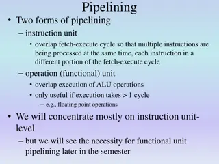
Basic Concept of Pipelining Circuit technology and hardware arrangement influence the speed of execution for programs All computer units benefit from faster circuits Pipelining involves arranging the hardware to perform multiple operations simultaneously Similar to assembly line where product moves through stations that perform specific tasks Same total time for each item, but different tasks are overlapped for different items (or instructions in processors)
Pipelining in a Computer Focus on pipelining of instruction execution 5-stage organization consists of: Fetch, Decode, Compute, Memory, Write We ve seen how instructions are fetched & executed one at a time with only one stage active in any cycle With pipelining, multiple stages are active simultaneously for different instructions Still 5 cycles to execute, but rate reaches 1 instruction per cycle Ideally, one instruction is completed at each cycle
Pipeline Organization Use program counter (PC) to fetch instructions A new instruction enters pipeline every cycle Carry along instruction-specific information as instructions flow through the different stages Use interstage buffers to hold this information These buffers incorporate RA, RB, RZ, RM, RY, IR, and PC-Temp registers The buffers also hold control signal settings
1 Fetch 2 Decode 3 Compute 4 Memory 5 Write
Pipelining Issues Consider two successive instructions Ijand Ij+1. Assume that the destination register of Ijmatches one of the source registers of Ij+1 Result of Ijis written to destination in cycle 5 But Ij+1reads old value of register in cycle 3 Due to pipelining, Ij+1computation is incorrect. So stall (delay) Ij+1until Ijwrites the new value Condition requiring this stall is a data hazard Decode
Data Dependencies Now consider the specific instructions Add R2, R3, #100 Subtract R9, R2, #30 Destination R2 of Add is a source for Subtract There is a data dependency between them because R2 carries data from Add to Subtract On non-pipelined datapath, result is available in R2 because Add completes before Subtract
Stalling the Pipeline With pipelined execution, old value is still in register R2 when Subtract is in Decode stage So stall Subtract for 3 cycles in Decode stage New value of R2 is then available in cycle 6
Details for Stalling the Pipeline (1) Control circuitry must recognize dependency while Subtract is being decoded in cycle 3 Interstage buffers carry register identifiers for source(s) and destination of instructions In cycle 3, compare destination identifier in Compute stage against source(s) in Decode R2 matches, so Subtract kept in Decode while Add is allowed to continue normally
Details for Stalling the Pipeline (2) Stall the Subtract instruction for 3 cycles by holding interstage buffer B1 contents steady But what happens after Add leaves Compute? Control signals are set in cycles 3 to 5 to create an implicit NOP (No-operation) in Compute NOP control signals in interstage buffer B2 create a cycle of idle time in each later stage The idle time from each NOP is called a bubble
clock cycle Add Subtract R9, R2, #30 R2, R3, #100 1 2 3 4 5 6 7 8 9 Add Sub Sub Sub Sub Add Nop Nop Nop Sub Add Nop Nop Nop Sub No write in the memory Add Nop Nop Nop Sub No write in the register R9 is written R2 is written Data hazard is detected
Operand Forwarding Operand forwarding handles dependencies without the penalty of stalling the pipeline For the preceding sequence of instructions, new value for R2 is available at end of cycle 3 Forward value to where it is needed in cycle 4
Add Subtract R9, R2, #30 R2, R3, #100 What happens if instr. are NOT consecutive? E.g. Add Or R4, R5, R6 Subtract R9, R2, #30 R2, R3, #100
Add Or R4, R5, R6 Subtract R9, R2, #30 R2, R3, #100 3 3 RY
Software Handling of Dependencies Compiler can generate & analyze instructions Data dependencies are evident from registers Compiler puts three explicit NOP instructions between instructions having a dependency Delay ensures new value available in register but causes total execution time to increase Compiler can optimize by moving instructions into NOP slots (if data dependencies permit) Leading to a smaller code size and shorter execution time
Add Subtract R9, R2, #30 R2, R3, #100 Compiler
Memory Delays (1) Memory delays can also cause pipeline stalls A cache memory holds instructions and data from the main memory, but is faster to access With a cache, typical access time is one cycle But a cache miss requires accessing slower main memory with a much longer delay In pipeline, memory delay for one instruction causes subsequent instructions to be delayed
Memory Delays (2) Example considering a memory access time of 3 clock cycles
Memory Delays (3) Even with a cache hit, a Load instruction may cause a short delay due to a data dependency One-cycle stall required for correct value to be forwarded to instruction needing that value Optimize with useful instruction to fill delay operand forwarding
Branch Delays Ideal pipelining: fetch each new instruction while the previous instruction is being decoded 1 2 3 4 5 6 7 Ij Ij+1 Ij+2 F D C M W F D C M W F D C M W Branch instructions may alter execution sequence, but they must be processed to know the effect Any delay for determining branch outcome may lead to an increase in total execution time Techniques to mitigate this effect are desired Understand branch behavior to find solutions
Unconditional Branches (1) Consider instructions Ij, Ij+1, Ij+2in sequence Ijis an unconditional branch with target Ik The target address, calculated using offset (which is available after the Decode stage) and [PC]+4, is known after the Compute stage In pipeline, target Ikis known for Ijin cycle 4, but instructions Ij+1, Ij+2fetched in cycles 2 & 3 Target Ikshould have followed Ijimmediately, so discard Ij+1, Ij+2and incur into a two-cycle penalty
Effect of branch penalty Ideally, 1 instr. per cycle w/ pipelining Branch instr. are executed frequently Roughly pBR= 20 % of the instr. executed by the processor (may be significantly larger than the number of branch instr. in the code, because of loops) A 2-cycle branch penalty increases the average number of cycles S per instr. by 40 % S = (1 pBR) x 1 + pBRx ( 1 + 2) = 1 + 2 x pBR= 1.4 S = 1 + BR, BR= 2 x pBR= 0.4 Things are a little bit better, as not all the conditional branches will be taken
Reducing the Branch Penalty (1) Reducing the Branch Penalty (1) In pipeline, adder for PC in the Instruction Address Generator block is used every cycle, so it In pipeline, adder for PC in the Instruction Address Generator block is used every cycle, so it cannot calculate the branch target address cannot calculate the branch target address Needs to be duplicate for pipeline execution pipeline execution Needs to be duplicate for
Reducing the Branch Penalty (2) In pipeline, adder for PC in the Instruction Address Generator block is used every cycle, so it cannot calculate the branch target address So introduce a second adder just for branches and place this second adder in the Decode stage to enable earlier determination of target address For previous example, now only Ij+1is fetched Only one instruction needs to be discarded The branch penalty for UNCONDITIONAL branches is reduced to one cycle
Reducing the Branch Penalty (3) Unconditional branch
Conditional Branches Consider a conditional branch instruction: Branch_if_[R5]=[R6] LOOP Requires not only target address calculation, but also requires comparison for condition In the 5-stage architecture, ALU performs the comparison Target address now calculated in Decode stage To maintain one-cycle penalty, a comparator just for branches must be inserted in Decode stage Higher hardware complexity
The Branch Delay Slot (1) Let both branch decision and target address be determined in Decode stage of pipeline Instruction immediately following a branch is always fetched, regardless of branch decision That next instruction is discarded with penalty, except when conditional branch is not taken Non-uniform behaviour between the two cases The location immediately following the branch is called the branch delay slot
The Branch Delay Slot (2) Instead of conditionally discarding instruction in delay slot, always let it complete execution Let compiler find an instruction before branch to move into slot, if data dependencies permit Called delayed branching due to reordering If useful instruction put in slot, penalty is zero If not possible, insert explicit NOP in delay slot for one-cycle penalty, whether or not taken Benefits of delayed branching depends on the possibility for the compiler to fill the branch delay slot (this happens for more than 70 % of the cases in many programs)
Branch Prediction A branch is decided in Decode stage (cycle 2) while following instruction is always fetched Following instruction may require discarding (or with delayed branching, it may be a NOP) Instead of discarding the following instruction, can we anticipate the actual next instruction? Two aims: (a) predict the branch decision (b) use prediction earlier in cycle 1
Static Branch Prediction Simplest approach: assume branch not taken Penalty if prediction disproved during Decode If branches are random , accuracy is 50% But a branch at end of a loop is usually taken So for backward branch, always predict taken Instead, always predict not taken for forward branch Expect higher accuracy for this special case, but what about accuracy for other branches? For the last iteration of loops, the static prediction is wrong
Dynamic Branch Prediction Idea: track branch decisions during execution for dynamic prediction to improve accuracy Simplest approach: use most recent outcome for likely taken (LT) or likely not-taken (LNT) For branch at end of loop, we mispredict in last pass, and in first pass if loop is re-entered Avoid misprediction for loop re-entry with four states (ST, LT, LNT, SNT) for strongly/likely Must be wrong twice to change prediction
In LNT and SNT states branch is predicted NOT TAKEN In LT and ST states branch is predicted as TAKEN
Branch Target Buffer Prediction only provides a presumed decision Decode stage computes target in cycle 2 But we need target (and prediction) in cycle 1 Branch target buffer stores target address and history from last execution of each branch. Each element of the buffer contains: the address of the branch instr., the state of the branch prediction alg and the branch target address In cycle 1, use branch instruction address to look up target and use history for prediction Fetch in cycle 2 using prediction; if mispredict detected during Decode, correct it in cycle 3
Performance Evaluation For a non-pipelined proc., the instr. throughput (#instr. per second) is: Fnp= R/S, where R is the clock freq. and S is the average number of cycles to execute one instr. For the 5-stage architecture, S = 5 assuming that every memory access can be performed in one cycle (no cache misses). For a pipelined proc., throughput F is increased by instr. execution overlapping. Ideally, S can be reduced to 1 (one instr. per cycle). This implies no pipeline stalls. How can we quantify the effect of pipeline stalls and branch penalties on achieved instr. throughput?
Effect of Stalls Let s consider a proc. w/ operand forwarding (in hardware). Stalls occur when data dependency is related to a Load instr., which causes a 1-cycle stall E.g. if freq. of Load instr. pLD= 25 %, freq. of data dependency after a Load pLD-dep= 40 %, then throughput F is reduced to: F = R/(1 + stall) where stall= 1xpLDxpLD-dep= 0.1 Thus, F = R/1.1 = 0.91R The compiler can improve performance by trying to reduce pLD-dep
Effect of Branch Penalty Let s consider a proc. w/ branch decision and branch target address evaluation in the Decode stage. When branch is mispredicted, there is 1-cycle penalty. E.g. if freq. of branch instr. pBR= 20 %, prediction accuracy pBR-pred= 90 %, then throughput F is reduced to: F = R/(1 + BR_penalty) where BR_penalty= 1xpBRx (1- pBR-pred) = 0.02 Thus, F = R/1.02 = 0.98R BR_penaltyadds to stall
Effect of Cache Misses When a cache miss occurs, there is a penalty due to the access of a slower memory which stalls the pipeline for Nmisscycles. E.g. if freq. of cache misses during fetch pmiss-fetch= 5 %, freq. of cache misses during mem access pmiss-mem= 10 %, freq. of Load and Store instr. pLD-ST= 30 %, Nmiss= 15, then throughput F is reduced to: F = R/(1 + cache-miss) where cache-miss= Nmiss(pmiss-fetch+ pLD-STx pmiss-mem) = 15x(0.05 + 0.03) = 1.2 Thus F = R/2.2 = 0.45R cache-miss adds to BR_penaltyand stall. Thus, overall F = R/2.32 = 0.42R Cache misses are the dominant factor.
Number of Pipeline Stages n ? , R clock frequency ? = 1 + ?penalty R increases with n (? ?, if n is low) However, also ?penalty increases with n because of higher probability of stalls, later branch decisions, higher cycle penalty, Choose so that ALU determins R (the other stages need similar times) To increase R further piplenine also ALU Up to 20 stages to have R in the order of GHz
Superscalar Operation Introduce multiple execution units to enable multiple instruction issue for higher than 1 instr./cycle throughput This organization is for a superscalar processor An elaborate fetch unit brings 2 or more instructions into an instruction queue in every cycle A dispatch unit takes 2 or more instructions from the head of the instr. queue in every cycle, decodes them, sends them to appropriate execution units A completion unit writes results to registers
Superscalar Processor (1) 2 execution units working in parallel
Superscalar Processor (2) Minimum superscalar arrangement consists of a Load/Store unit and an arithmetic unit Because of Index mode address calculation, Load/Store unit has a two-stage pipeline Arithmetic unit usually has one stage For two execution units, how many operands? Up to 4 inputs, so register file has 4 read ports Up to 2 results, so also need 2 write ports (and methods to prevent write to the same reg.)
Branches and Data Dependencies (1) With no branches or data dependencies, interleave arithmetic & memory instructions to obtain maximum throughput (2 per cycle) But branches do occur and must be handled Branches processed entirely by fetch unit to determine which instructions enter queue Fetch unit uses prediction for all branches Necessary because decisions may need values produced by other instructions in progress
Branches and Data Dependencies (2) Speculative execution: results of instructions not committed until prediction is confirmed Requires extra hardware to track speculation and to recover in the event of misprediction For data dependencies between instructions, the execution units have reservation stations They buffer register identifiers and operands for dispatched instructions awaiting execution Broadcast results for stations to capture & use
Out-of-Order Execution With instructions buffered at execution units, should execution reflect original sequencing? If two instructions have no dependencies, there are no actual ordering constraints This enables out-of-order execution, but then leads to imprecise exceptions For precise exceptions, results must strictly be committed in original order. This requires additional hardware
Execution Completion To commit results in original program order, superscalar processors can use 2 techniques Register renaming uses temporary registers to hold new data before it is safe to commit them in the register file Reorder buffer in commitment unit is where dispatched instructions are placed strictly in the program order Update the actual destination register only for instruction at the head of reorder buffer queue Ensures instructions retired in original order
Dispatch Operation Dispatch of instruction proceeds only when all needed resources available (temp. register, space in reservation station & reorder buffer) If instruction has some but not all resources, should a subsequent instruction proceed? Decisions must avoid deadlock conditions (two instructions need each other s resources) More complex, so easier to use original order, particularly with more than 2 execution units


")
")


")
")
")

")
")

")
")
")

")
")
")


")
")

")
")