Understanding Processor Structure and Function in Computing
Explore the key components and functions of processors in computing, including user-visible and control status registers, instruction cycle, instruction pipelining, processor tasks like data processing and instruction interpretation, and the roles of arithmetic and logic units and control units. Learn about the crucial tasks a processor must accomplish and how data is processed within the system.

Download Presentation

Please find below an Image/Link to download the presentation.
The content on the website is provided AS IS for your information and personal use only. It may not be sold, licensed, or shared on other websites without obtaining consent from the author. Download presentation by click this link. If you encounter any issues during the download, it is possible that the publisher has removed the file from their server.
E N D
Presentation Transcript
Eastern Mediterranean University School of Computing and Technology Master of Technology Chapter Chapter 14 14 Processor Structure and Function Processor Structure and Function
Learning Objectives After studying this chapter, you should be able to: Distinguish between user-visible and control/status registers, and discuss the purposes of registers in each category. Summarize the instruction cycle. Discuss the principle behind instruction pipelining and how it works in practice. Compare and contrast the various forms of pipeline hazards 2
What are the tasks that a processor must accomplish? Fetch instruction from memory (register, cache, main memory) Interpret determine what action is required Fetch require reading data from memory or an I/O module Fetch instruction instruction: : The processor reads an Interpret instruction instruction: : The instruction is decoded to Fetch data data: : The execution of an instruction may 3
Process data require performing some arithmetic or logical operation on data Write data writing data to memory or an I/O module Process data: : The execution of an instruction may Write data: : The results of an execution may require In order to do these things the processor needs to store some data temporarily therefore needs a small internal memory These storage locations are called registers temporarily and small internal memory. registers. 4
Notice that the major components of the processor are an arithmetic and logic unit (ALU) and a control unit (CU). The ALU does the actual computation or processing of data. arithmetic and logic unit What are the functions of control unit? The control unit controls the movement of data instructions controls the operation of the ALU movement of data and instructions into and out operation of the ALU. into and out of the processor and 5
CPU with the system bus CPU with the system bus 6
ALU operates only processor memory. only on data in the internal Thus, data transfer between the various registers and ALU is needed which is the responsibility of internal processor bus internal processor bus. 7
Internal structure of the CPU Internal structure of the CPU 8
What general roles are performed by processor registers? The registers in the processor perform two roles: User assembly language programmer to minimize main memory references by optimizing use of registers. Control and status registers unit to control the operation of the processor operating system programs to control the execution of programs. two roles: User- -visible registers visible registers: : Enable the machine- or Control and status registers: : Used by the control control the operation of the processor and control the execution of programs. 9
A user-visible register is one that may be referenced by means of the machine language that the processor executes. What categories of data are commonly supported by user We can characterize these in the following categories: General purpose registers(data, address) Data registers Address registers Condition codes (flags) user- -visible registers visible registers? 10
General Registers or General Purpose Registers are a kind of registers which can store both data and addresses Data registers may be used only to hold data and cannot be employed in the calculation of an operand address. Address registers may themselves be somewhat general purpose, or they may be devoted to a particular addressing mode. Examples include the following Segment pointers: Index registers: Stack pointer What is the function of condition codes? Condition codes They are bits set by the processor hardware as the result of operations. For example, an arithmetic operation may produce a positive, negative, zero, or overflow result. 11
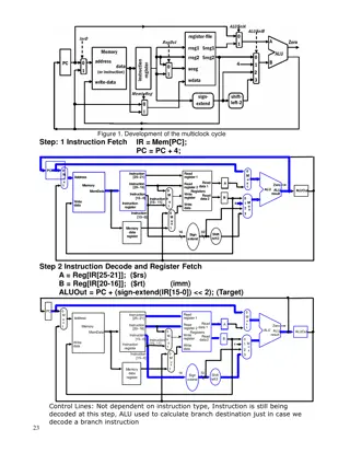
Four registers execution: Program counter (PC): instruction Instruction register (IR): defines the type of instruction. Memory address register (MAR address of a location in memory Memory buffer register (MBR): data recently read Four registers are essential execution: Program counter (PC): holds the address of instruction to be fetched Instruction register (IR): holds the opcode essential to instruction to instruction address of the next the next holds the opcode which Memory address register (MAR): ): Contains the address of a location in memory Memory buffer register (MBR): Contains a word of data to be written to memory or the word most Contains the Contains a word of 12
Typically, the processor updates the PC after each instruction fetch so that the PC always points to the next instruction to be executed. A branch or skip instruction will also modify the contents of the PC. The fetched instruction is loaded into an IR, where the opcode and operand specifiers are analyzed. Data are exchanged with memory using the MAR and MBR. 13
What is a program status word? Many processor designs include a register or set of registers, often known as the program status word (PSW) information. What is a program status word? program status status word (PSW), that contain status information. The PSW typically contains condition codes plus other status information. 14
Common fields or flags include the following: Sign Zero Carry Equal Overflow Interrupt Enable/Disable interrupts) Supervisor Sign (sign bit of the last arithmetic operation) Zero (set when the result is 0) Carry (set if an operation resulted in a carry) Equal (set if a logical compare result is equality) Overflow (used to indicate arithmetic overflow) Interrupt Enable/Disable (used to enable or disable Supervisor (used to indicate supervisor or user mode) 15
The Motorola MC68000 partitions its 32-bit registers into eight data registers and nine address registers. Data registers are used primarily for data manipulation and are also used in addressing as index registers. The width of the registers allows 8-, 16-, and 32-bit data operations, determined by opcode. The MC68000 also includes a 32-bit program counter and a 16-bit status register. Motorola MC68000 (16-bit microprocessor) 17
The Intel 8086 different approach to register organization. Every register is special purpose, although some registers are also usable as general purpose. The 8086 contains four 16-bit data registers. The data registers can be used as general purpose in some instructions. Three of the four segment registers are used in to point to the segment of the current instruction. Intel 8086 (16-bit microprocessor) takes a 18
The Intel 80386 microprocessors) uses 32-bit registers. However, to provide upward compatibility for programs written on the earlier machine, the 80386 retains the original register organization embedded in the new organization. Given this design constraint, the architects of the 32-bit processors had limited flexibility in designing the register organization. Intel 80386- -Pentium 4 Pentium 4 (32-bit 19
An instruction cycle includes the following stages: Fetch processor. Execute: indicated operation. Interrupt has occurred, save the current process state and service the interrupt. Fetch: : Read the next instruction from memory into the Execute: Interpret the opcode and perform the Interrupt: : If interrupts are enabled and an interrupt 20
We are now introduce one additional stage, known as the indirect cycle The Indirect Cycle if indirect addressing is used, then additional memory accesses are required. After an instruction is fetched, it is examined to determine if any indirect addressing is involved. If so, the required operands are fetched using indirect addressing. Following execution, an interrupt may be processed before the next instruction fetch 21
Once an instruction is fetched, its operand specifiers must be identified. Each input operand in memory is then fetched, and this process may require indirect addressing. Register-based operands need not be fetched. Once the opcode is executed, a similar process may be needed to store the result in main memory. Following execution, an interrupt may be processed before the next instruction fetch. 23
During the fetch cycle; The PC contains the address of the next instruction to be fetched. This address is moved to the MAR and placed on the address bus. The control unit requests a memory read, and the result is placed on the data bus and copied into the MBR and then moved to the IR. Meanwhile, the PC is incremented by 1, preparatory for the next fetch. Fetch Cycle 25
Once the fetch cycle is over, the control unit examines the contents of the IR to determine if it contains an operand specifier using indirect addressing. If so, an indirect cycle is performed The rightmost N bits of the MBR, which contain the address reference, are transferred to the MAR. Then the control unit requests a memory read, to get the desired address of the operand into the MBR. Indirect Cycle 26
The execute cycle depends on which of the various machine instructions is in the IR. execute cycle takes many forms; the form This cycle may involve transferring data among registers, read or write from memory or I/O, and/or the invocation of the ALU. 27
The current contents of the PC must be saved so that the processor can resume normal activity after the interrupt. Thus, the contents of the PC are transferred to the MBR to be written into memory. The special memory location reserved for this purpose is loaded into the MAR from the control unit. It might, for example, be a stack pointer. The PC is loaded with the address of the interrupt routine. As a result, the next instruction cycle will begin by fetching the appropriate instruction Data flow of Interrupt Cycle 28
3 3. .Instruction Pipelining Instruction Pipelining To improve the performance of a CPU we have two options: 1) Improve the hardware by introducing faster circuits. 2) Arrange the hardware such that more than one operation can be performed at the same time. Since, there is a limit on the speed of hardware and the cost of faster circuits is quite high, we have to adopt the 2nd option. 29
Pipelining is a process of arrangement of hardware elements of the CPU such that its overall performance is increased. Simultaneous execution of more than one instruction takes place in a pipelined processor. Let us see a real life example that works on the concept of pipelined operation. Consider a water bottle packaging plant. Let there be 3 stages that a bottle should pass through, Inserting the bottle (I), Filling water in the bottle (F), and Sealing the bottle (S). Let us consider these stages as stage 1, stage 2 and stage 3 respectively. Let each stage take 1 minute to complete its operation. 30
Thus, pipelined operation increases the efficiency of a system. 31
As a simple approach, consider subdividing instruction processing into two stages: fetch instruction and execute instruction. There are times during the execution of an instruction when main memory is not being accessed. This time could be used to fetch the next instruction in parallel with the execution of the current one. The pipeline has two independent stages. The first stage fetches an instruction and buffers it. When the second stage is free, the first stage passes it the buffered instruction. While the second stage is executing the instruction, the first stage takes advantage of any unused memory cycles to fetch and buffer the next instruction. This is called instruction prefetch or fetch overlap 32
It should be clear that this process will speed up instruction execution. If the fetch and execute stages were of equal duration, the instruction cycle time would be halved Two-Stage Instruction Pipeline 33
Note that this approach, which involves instruction buffering, requires more registers. In general, pipelining requires registers to store data between stages. 34
To gain further speedup, the pipeline must have more stages.(6th stage pipeline) Consider the following decomposition of the instruction processing. Fetch instruction (FI) Read the next expected instruction into a buffer Decode instruction (DI) Determine the opcode and the operand specifiers Calculate operands (CO) Calculate the effective address of each source operand Fetch operands (FO) Fetch each operand from memory,Operands in registers need not be fetched Execute instruction (EI) Perform the indicated operation and store the result, if any, in the specified destination operand location Write operand (WO) Store the result in memory 35
With this decomposition, the various stages will be of more nearly equal duration. For the sake of illustration, let us assume equal duration. Using this assumption, Figure below shows that a six- stage pipelinecan reduce the execution time for 9 instructions from 54 time units to 14 time units Timing diagram for instruction pipeline operation with 9 instructions. 36
The diagram assumes that each instruction goes through all six stages of the pipeline where each step has equal duration In particular, it is assumed that there are no memory conflicts. For example, the FI, FO, and WO stages involve a memory access. However, the desired value may be in cache, or the FO or WO stage may be null. Thus, much of the time, memory conflicts will not slow down the pipeline. equal duration. 37
A possible difficulty is the conditional branch instruction instruction fetches. A similar unpredictable event is an interrupt branch instruction, which can invalidate several interrupt. The branch operations in the pipelined is known as branch penalty The number of stalls branch operations in the pipelined processor branch penalty. number of stalls introduced during the introduced during the 38
Example pipeline operation. Example: : The effect of a conditional branch effect of a conditional branch on instruction 39
Assume that instruction 3 is a conditional branch to instruction 15. Until the instruction is executed, there is no way of knowing which instruction will come next. The pipeline, in this example, simply loads the next instruction in sequence (instruction 4) and proceeds. 40
This is not determined until t=7. At this point, the pipeline must be cleared of instructions that are not useful. During t=8, instruction 15 enters the pipeline. No instructions complete during time units 9 through 12; this is the performance penalty incurred because we could not anticipate the branch. 41
Figure indicates the logic needed for pipelining to account for branches and interrupts. 42
The cycle time of an instruction pipeline is the time needed to advance a set of instructions one stage through the pipeline. The cycle time can be determined as
In general, the time delay d is equivalent to a clock pulse and Now suppose that n instructions are processed, with no branches. Let be the total time required for a pipeline with k stages to execute n instructions. Then For example, the ninth instruction completes at time cycle 14 44
The speedup factor for the instruction pipeline compared to execution without the pipeline is defined as As might be expected, at the limit we have a k-fold speedup 45
Instruction pipelining is a powerful technique for enhancing performance but requires careful design to achieve optimum results with reasonable complexity. 46
Occur when the pipeline, or some portion of the pipeline, must stall because conditions do not permit continued execution. Also referred to as a pipeline bubble. Any condition that causes a stall in the pipeline operations can be called a There are three types of hazards Resource hazard Data hazard Control hazard Any condition that causes a stall in the pipeline operations can be called a hazard. three types of hazards: 47
A resource hazard instructions that are already in the pipeline need the same resource. resource hazard occurs when two or more instructions that are already in the pipeline need the same resource. occurs when two or more The result is that the instructions must be executed in portion of the pipeline. instructions must be executed in serial rather than parallel for a A resource hazard is sometimes referred to as a structural hazard. 48
Let us consider a simple example of a resource hazard. Assume a simplified five-stage pipeline, in which each stage takes one clock cycle. Figure below shows the ideal case, in which a new instruction enters the pipeline each clock cycle. 49
Now assume that main memory has a single port and that all instruction fetches and data reads and writes must be performed one at a time. Further, ignore the cache. In this case, an operand read to or write from memory cannot be performed in parallel with an instruction fetch. 50