Innovative Air Piano Project with Arduino Microcontroller

Explore the creation of an interactive air piano using Arduino microcontroller, photoresistors, sensors, and a control module for volume and effects manipulation. The project involves swiping fingers over holes to trigger keys, communicating with a PC via MIDI, and integrating various components for a unique musical experience.

Download Presentation

Please find below an Image/Link to download the presentation.
The content on the website is provided AS IS for your information and personal use only. It may not be sold, licensed, or shared on other websites without obtaining consent from the author. Download presentation by click this link. If you encounter any issues during the download, it is possible that the publisher has removed the file from their server.
E N D
Presentation Transcript
Create an air piano, with keys triggered by swiping fingers on top of several holes Communicate with a PC via MIDI Build a control module with sensors which change volume and sound effects 2
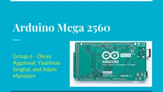
Microcontroller Arduino Micro Keyboard Photoresistors 1 k resistors Cardboard structure Control module Ultrasonic sensor (velocity control) Accelerometer (effects control) Breadboard structure 3
Microcontroller Operating Voltage Input Voltage (recommended) Input Voltage (limits) Digital I/O Pins PWM Channels Analog Input Channels DC Current per I/O Pin DC Current for 3.3V Pin ATmega32u4 5V 7-12V 6-20V 20 7 12 40 mA 50 mA 32 KB (ATmega32u4) of which 4 KB used by bootloader 2.5 KB (ATmega32u4) 1 KB (ATmega32u4) 16 MHz Flash Memory SRAM EEPROM Clock Speed 5
Resistance decreases with increasing incident light intensity. 6
Provides precise, non-contact distance measurements within a 2 cm to 3 m range Ultrasonic measurements work in any lighting condition, making this a good choice to supplement infrared object detectors Simple pulse in/pulse out communication requires just one I/O pin 7
Measures 3 g on each axis, enough for data for a wide variety of applications Simple pulse output of g-force for each axis is easy to read for most any microcontroller Analog output of temperature (Tout pin) allows for fine-tuning of advanced applications Low current at 3.3 or 5 V operation (less than 4 mA at 5 VDC) puts low demand on the system 8
Musical Instrument Digital Interface Created in 1983 Analog to music notation Does not include sound information Open-Source Small messages Simple communication protocol Status bytes and data bytes 9
Status D7----D0 Data Byte(s) D7----D0 Description 1001nnnn 0kkkkkkk 0vvvvvvv Note On event. This message is sent when a note is depressed (start). (kkkkkkk) is the key (note) number. (vvvvvvv) is the velocity. 1011nnnn 0ccccccc 0vvvvvvv Control Change. This message is sent when a controller value changes. Controllers include devices such as pedals and levers. Controller numbers 120-127 are reserved as "Channel Mode Messages" (below). (ccccccc) is the controller number (0-119). (vvvvvvv) is the controller value (0-127). 10
There is an automated calibration routine for the photoresistors, since they are highly influenced by ambient light When a photoresistor senses a shade, the correspondent note is triggered and sent to the PC The values read by the ultrasonic sensor and accelerometer are translated to MIDI commands 11
This project has several applications since inexpensive gesture sensing is important nowadays Socially assistive robots and devices Remote controllers Alternative computer interfaces DJ equipment Toys and video games 13
Pictures and information taken from: www.arduino.cc www.parallax.com www.midi.org 14