Caterpillar Cat CS-433E, CP-433E Vibratory Compactor (Prefix CYE) Service Repair Manual Instant Download
Please open the website below to get the complete manualnn//
Download Presentation

Please find below an Image/Link to download the presentation.
The content on the website is provided AS IS for your information and personal use only. It may not be sold, licensed, or shared on other websites without obtaining consent from the author. Download presentation by click this link. If you encounter any issues during the download, it is possible that the publisher has removed the file from their server.
E N D
Presentation Transcript
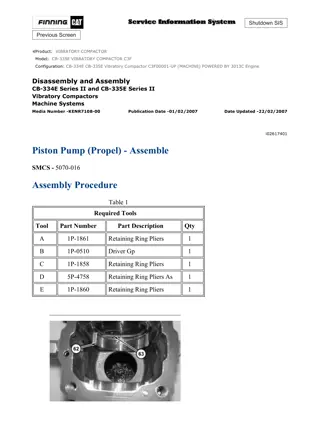
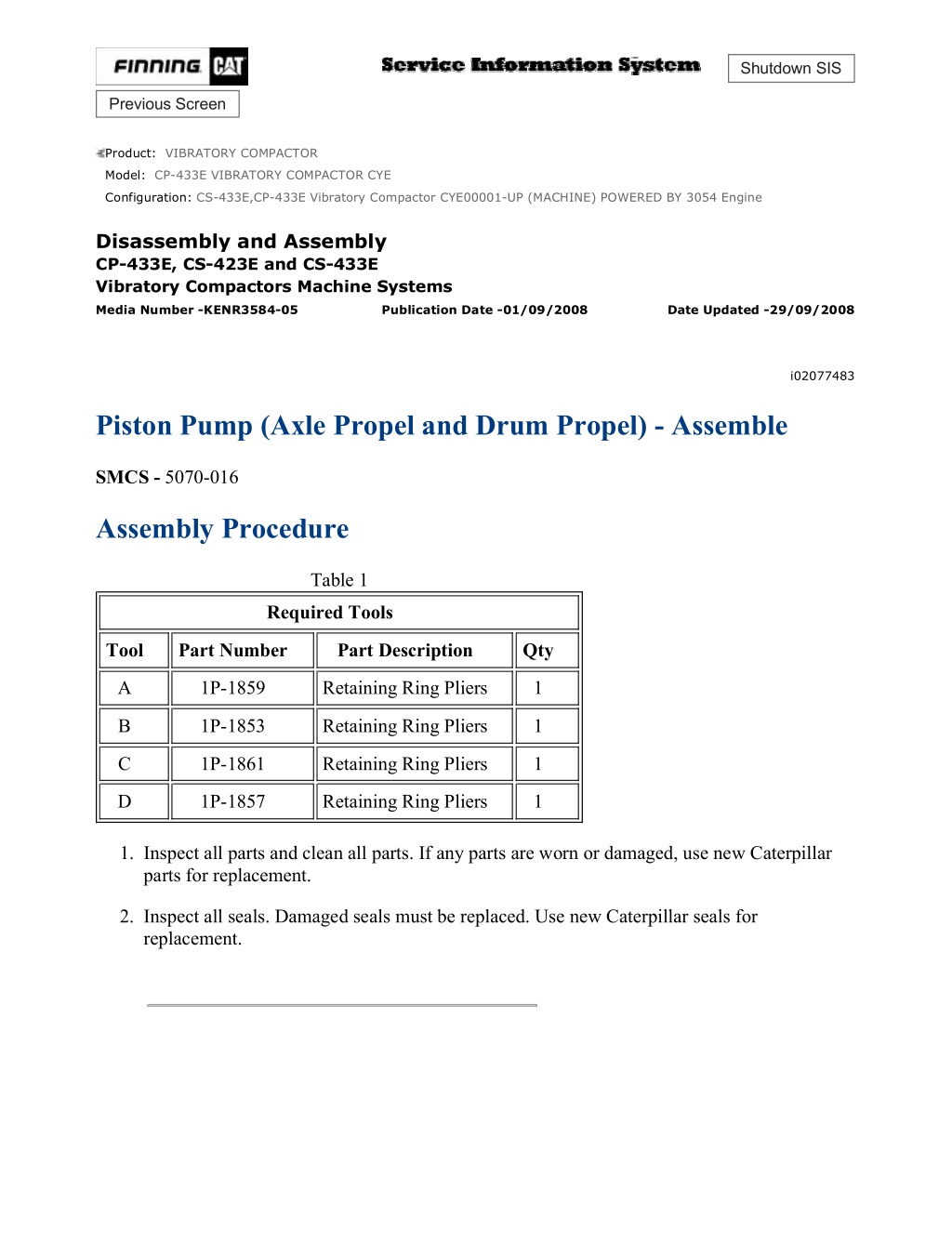
CS-433E,CP-433E Vibratory Compactor CYE00001-UP (MACHINE) POWERED B... 1/25 Shutdown SIS Previous Screen Product: VIBRATORY COMPACTOR Model: CP-433E VIBRATORY COMPACTOR CYE Configuration: CS-433E,CP-433E Vibratory Compactor CYE00001-UP (MACHINE) POWERED BY 3054 Engine Disassembly and Assembly CP-433E, CS-423E and CS-433E Vibratory Compactors Machine Systems Media Number -KENR3584-05 Publication Date -01/09/2008 Date Updated -29/09/2008 i02077483 Piston Pump (Axle Propel and Drum Propel) - Assemble SMCS - 5070-016 Assembly Procedure Table 1 Required Tools Tool Part Number Part Description Qty A 1P-1859 Retaining Ring Pliers 1 B 1P-1853 Retaining Ring Pliers 1 C 1P-1861 Retaining Ring Pliers 1 D 1P-1857 Retaining Ring Pliers 1 1. Inspect all parts and clean all parts. If any parts are worn or damaged, use new Caterpillar parts for replacement. 2. Inspect all seals. Damaged seals must be replaced. Use new Caterpillar seals for replacement. https://127.0.0.1/sisweb/sisweb/techdoc/techdoc_print_page.jsp?returnurl=/sis... 2021/4/24
CS-433E,CP-433E Vibratory Compactor CYE00001-UP (MACHINE) POWERED B... 2/25 Illustration 1 g01067503 Sudden release of spring force can cause injury. To prevent the possibility of injury, follow the procedure to relieve the spring pressure. 3. Install O-ring seal (108) on charge relief plug (109). Install poppet (106), spring (107), and charge relief plug (109) in propel pump (1) . Illustration 2 g01067497 4. Install O-ring seals (104) on servo assembly (101) . https://127.0.0.1/sisweb/sisweb/techdoc/techdoc_print_page.jsp?returnurl=/sis... 2021/4/24
CS-433E,CP-433E Vibratory Compactor CYE00001-UP (MACHINE) POWERED B... 3/25 Illustration 3 g01067495 5. Install rings (103) on servo assembly (101) . Illustration 4 g01067491 6. Install bearing (102) in servo assembly (101) . 7. Install gasket (100) on cover (97) . 8. Install cover (97) on servo assembly (101) . https://127.0.0.1/sisweb/sisweb/techdoc/techdoc_print_page.jsp?returnurl=/sis... 2021/4/24
https://www.ebooklibonline.com Hello dear friend! Thank you very much for reading. Enter the link into your browser. The full manual is available for immediate download. https://www.ebooklibonline.com
CS-433E,CP-433E Vibratory Compactor CYE00001-UP (MACHINE) POWERED B... 4/25 Illustration 5 g00856427 9. Install the servo assembly in propel pump (1) and install screws (96). Tighten the screws to a torque of 16 1 N m (12 1 lb ft). 10. Install seal nut (98) on cover (97) . 11. Install the O-ring seal on plug (99). Install plug (99) in cover (97) . Illustration 6 g00856423 12. Install the gasket, cover (94), and screws (93) on propel pump (1). Tighten the screws (93) to a torque of 16 1 N m (12 1 lb ft). 13. Install the O-ring seal on plug (95). Install plug (95) on cover (94) . Illustration 7 g00856432 14. Repeat Steps 4 through 13 in order to install servo assembly (105) . https://127.0.0.1/sisweb/sisweb/techdoc/techdoc_print_page.jsp?returnurl=/sis... 2021/4/24
CS-433E,CP-433E Vibratory Compactor CYE00001-UP (MACHINE) POWERED B... 5/25 Illustration 8 g00856421 15. Install the coupling and bearings (92) on the inside of propel pump (1) . Illustration 9 g00856420 16. Install swashplate (91) in propel pump (1) . Illustration 10 g00856419 17. Install valve plate (90) and pin (89) in propel pump (1) . https://127.0.0.1/sisweb/sisweb/techdoc/techdoc_print_page.jsp?returnurl=/sis... 2021/4/24
CS-433E,CP-433E Vibratory Compactor CYE00001-UP (MACHINE) POWERED B... 6/25 Illustration 11 g00856417 Illustration 12 g00856416 Sudden release of spring force can cause injury. To prevent the possibility of injury, follow the procedure to relieve the spring pressure. 18. Install washer (87), spring (88), and washer (86) in cylinder block (81) . 19. Put cylinder block (81) in a suitable press. Install a suitable drive plate of the same size as washer (86). Put slight compression on washer (86) with the press. Use Tooling (D) to install retaining ring (85). Slowly release the spring compression. https://127.0.0.1/sisweb/sisweb/techdoc/techdoc_print_page.jsp?returnurl=/sis... 2021/4/24
CS-433E,CP-433E Vibratory Compactor CYE00001-UP (MACHINE) POWERED B... 7/25 Illustration 13 g00856414 20. Install pin retainer (84), pins (83), and slipper retainer guide (82) on cylinder block (81) . Illustration 14 g00856412 21. Install slipper retainer (80) and piston assemblies (79) into cylinder block (81) . Illustration 15 g00856410 22. Install cylinder block assembly (78) into propel pump (1) . https://127.0.0.1/sisweb/sisweb/techdoc/techdoc_print_page.jsp?returnurl=/sis... 2021/4/24
CS-433E,CP-433E Vibratory Compactor CYE00001-UP (MACHINE) POWERED B... 8/25 Illustration 16 g00856409 23. Install bearing (77). Use Tooling (A) to install retaining ring (76) on shaft (1) . Illustration 17 g00856407 24. Install shaft (75) into propel pump (75) . https://127.0.0.1/sisweb/sisweb/techdoc/techdoc_print_page.jsp?returnurl=/sis... 2021/4/24
CS-433E,CP-433E Vibratory Compactor CYE00001-UP (MACHINE) POWERED B... 9/25 Illustration 18 g00856406 25. Install lip seal (74) and O-ring seal (73) in seal cover (72) . Illustration 19 g00856405 26. Install seal cover (72). Use Tooling (C) to install retaining ring (71) in propel pump (1) . Illustration 20 g00856404 27. Install gasket (70) on propel pump (1) . https://127.0.0.1/sisweb/sisweb/techdoc/techdoc_print_page.jsp?returnurl=/sis... 2021/4/24
CS-433E,CP-433E Vibratory Compactor CYE00001-UP (MACHINE) POWERED ... 10/25 Illustration 21 g00856403 28. Install cover (69) on propel pump (1). Install new bolts (69). Tighten the bolts (69) to a torque of 38 5 N m (28 4 lb ft). Illustration 22 g00856402 29. Install swashplate (67) into propel pump (1) . Illustration 23 g00856400 https://127.0.0.1/sisweb/sisweb/techdoc/techdoc_print_page.jsp?returnurl=/sis... 2021/4/24
CS-433E,CP-433E Vibratory Compactor CYE00001-UP (MACHINE) POWERED ... 11/25 30. Install valve plate (66) and pin (65) in propel pump (1) . Illustration 24 g00856399 Illustration 25 g00856398 Sudden release of spring force can cause injury. To prevent the possibility of injury, follow the procedure to relieve the spring pressure. 31. Install washer (63), spring (64), and washer (62) in cylinder block (57) . 32. Put cylinder block (57) in a suitable press. Install a suitable drive plate of the same size as washer (62). Put slight compression on washer (62) with the press. Use Tooling (D) to install retaining ring (61). Slowly release the spring compression. https://127.0.0.1/sisweb/sisweb/techdoc/techdoc_print_page.jsp?returnurl=/sis... 2021/4/24
CS-433E,CP-433E Vibratory Compactor CYE00001-UP (MACHINE) POWERED ... 12/25 Illustration 26 g00856396 33. Install pin retainer (60), three pins (59), and slipper retainer guide (58) on cylinder block (57) . Illustration 27 g00856395 34. Install slipper retainer (56) and piston assemblies (55) into cylinder block (57) . Illustration 28 g00856394 https://127.0.0.1/sisweb/sisweb/techdoc/techdoc_print_page.jsp?returnurl=/sis... 2021/4/24
CS-433E,CP-433E Vibratory Compactor CYE00001-UP (MACHINE) POWERED ... 13/25 35. Install cylinder block assembly (54) into propel pump (1) . Illustration 29 g00856393 36. Raise the temperature of the bearing (53) and install the bearing (53) on the shaft (52) . Illustration 30 g00856392 37. Install shaft (52). Use Tooling (C) to install retaining ring (51) in propel pump (1) . https://127.0.0.1/sisweb/sisweb/techdoc/techdoc_print_page.jsp?returnurl=/sis... 2021/4/24
CS-433E,CP-433E Vibratory Compactor CYE00001-UP (MACHINE) POWERED ... 14/25 Illustration 31 g00856391 38. Install gasket (50) on propel pump (1) . Illustration 32 g00856389 39. Install cover (49) on propel pump (1). Install new bolts (48). Tighten the bolts (48) to a torque of 38 5 N m (28 4 lb ft). Illustration 33 g00856388 40. Install O-ring seal (47) on propel pump (1) . https://127.0.0.1/sisweb/sisweb/techdoc/techdoc_print_page.jsp?returnurl=/sis... 2021/4/24
CS-433E,CP-433E Vibratory Compactor CYE00001-UP (MACHINE) POWERED ... 15/25 Illustration 34 g00856387 41. Install mounting flange (46) and bolts (45) . Illustration 35 g00856385 Illustration 36 g00856383 42. Install the O-ring seals and bypass valve (43). Use Tooling (B) to install retaining ring (42) in bypass valve assembly (38) . https://127.0.0.1/sisweb/sisweb/techdoc/techdoc_print_page.jsp?returnurl=/sis... 2021/4/24
CS-433E,CP-433E Vibratory Compactor CYE00001-UP (MACHINE) POWERED ... 16/25 43. Install backup ring (40), O-ring seal (41), and O-ring seal (39) on the bypass valve assembly. Illustration 37 g00856382 Sudden release of spring force can cause injury. To prevent the possibility of injury, follow the procedure to relieve the spring pressure. 44. Install spring (36) and relief valve (37). Install bypass valve assembly (38) in propel pump (1) . 45. Repeat Steps 42 through 44 in order to install the remaining bypass valve assemblies and the relief valves. Illustration 38 g00856380 https://127.0.0.1/sisweb/sisweb/techdoc/techdoc_print_page.jsp?returnurl=/sis... 2021/4/24
CS-433E,CP-433E Vibratory Compactor CYE00001-UP (MACHINE) POWERED ... 17/25 46. Install seal nut (34) fromneutral adjustment screw (33) . Illustration 39 g00856378 47. Install neutral adjustment screw (33) . Illustration 40 g00856381 48. Repeat Steps 46 and 47 in order to install neutral adjustment screw (35) . https://127.0.0.1/sisweb/sisweb/techdoc/techdoc_print_page.jsp?returnurl=/sis... 2021/4/24
CS-433E,CP-433E Vibratory Compactor CYE00001-UP (MACHINE) POWERED ... 18/25 Illustration 41 g00856375 49. Install the O-ring seal on the plug. Install plug (31) on propel pump (1) . Illustration 42 g00856373 Sudden release of spring force can cause injury. To prevent the possibility of injury, follow the procedure to relieve the spring pressure. 50. Install O-ring seal (29) on plug (30). Install spool assembly (26) in propel pump (1). Install control spring adapter (27), control spring (28), and plug (30) in the propel pump. Illustration 43 g00856377 https://127.0.0.1/sisweb/sisweb/techdoc/techdoc_print_page.jsp?returnurl=/sis... 2021/4/24
CS-433E,CP-433E Vibratory Compactor CYE00001-UP (MACHINE) POWERED ... 19/25 51. Repeat Steps 49 and 50 in order to install control spool assembly (32) . Illustration 44 g00856371 52. Install adjusting links, feedback links (25), and screws (24). Tighten the screws (24) to a torque of 11 3 N m (8 2 lb ft). Illustration 45 g00856370 53. Install summing links (23) . https://127.0.0.1/sisweb/sisweb/techdoc/techdoc_print_page.jsp?returnurl=/sis... 2021/4/24
CS-433E,CP-433E Vibratory Compactor CYE00001-UP (MACHINE) POWERED ... 20/25 Illustration 46 g00856368 54. Install gaskets (22) on propel pump (1) . Illustration 47 g00856367 55. Install O-ring seal (21) on neutral start switch (20) . Illustration 48 g00856365 56. Install neutral start switch (20) on control housing (6) . https://127.0.0.1/sisweb/sisweb/techdoc/techdoc_print_page.jsp?returnurl=/sis... 2021/4/24
CS-433E,CP-433E Vibratory Compactor CYE00001-UP (MACHINE) POWERED ... 21/25 Illustration 49 g00856364 57. Install O-ring seal (19) on neutral start switch (18) . Illustration 50 g00856363 58. Install neutral start switch (18) on control housing (7) . https://127.0.0.1/sisweb/sisweb/techdoc/techdoc_print_page.jsp?returnurl=/sis... 2021/4/24
CS-433E,CP-433E Vibratory Compactor CYE00001-UP (MACHINE) POWERED ... 22/25 Illustration 51 g00856362 Sudden release of spring force can cause injury. To prevent the possibility of injury, follow the procedure to relieve the spring pressure. 59. Install O-ring seal (16) on stem (17). Install spool (13), spacer (14), spring (15), and stem (17) in control housing (7) . Illustration 52 g00856360 60. Use Tooling (A) to install retaining ring (12) . Illustration 53 g00856359 https://127.0.0.1/sisweb/sisweb/techdoc/techdoc_print_page.jsp?returnurl=/sis... 2021/4/24
CS-433E,CP-433E Vibratory Compactor CYE00001-UP (MACHINE) POWERED ... 23/25 61. Install the washer, solenoid (10), and nut (11). Tighten the nut (11) to a torque of 5.4 1.0 N m (47.8 8.9 lb in). Illustration 54 g00856358 62. Install O-ring seals (8) on connecting tube (9). Install connecting tube (9) and connect control housing (6) and control housing (7) . Illustration 55 g00856357 63. Install control assembly (6) and control assembly (7) as a unit on the propel pump. Install screws (5). Tighten the screws (5) to a torque of 16 1.4 N m (12 1 lb ft). https://127.0.0.1/sisweb/sisweb/techdoc/techdoc_print_page.jsp?returnurl=/sis... 2021/4/24
CS-433E,CP-433E Vibratory Compactor CYE00001-UP (MACHINE) POWERED ... 24/25 Illustration 56 g00856356 64. Install plugs (4) . Illustration 57 g00856355 https://127.0.0.1/sisweb/sisweb/techdoc/techdoc_print_page.jsp?returnurl=/sis... 2021/4/24
CS-433E,CP-433E Vibratory Compactor CYE00001-UP (MACHINE) POWERED ... 25/25 Illustration 58 g00858250 65. Install hub (3) on propel pump (1). Set Dimension (X) to 71.8 1.0 mm (2.83 0.04 inch). 66. Tighten bolt (2) to a torque of 86 10 N m (63 7 lb ft). End By: Install the piston pump (axle propel and drum propel). Refer to Disassembly and Assembly, "Piston Pump (Axle Propel and Drum Propel) - Install". Copyright 1993 - 2021 Caterpillar Inc. Sat Apr 24 08:48:08 UTC+0800 2021 All Rights Reserved. Private Network For SIS Licensees. https://127.0.0.1/sisweb/sisweb/techdoc/techdoc_print_page.jsp?returnurl=/sis... 2021/4/24
CS-433E,CP-433E Vibratory Compactor CYE00001-UP (MACHINE) POWERED B... 1/4 Shutdown SIS Previous Screen Product: VIBRATORY COMPACTOR Model: CP-433E VIBRATORY COMPACTOR CYE Configuration: CS-433E,CP-433E Vibratory Compactor CYE00001-UP (MACHINE) POWERED BY 3054 Engine Disassembly and Assembly CP-433E, CS-423E and CS-433E Vibratory Compactors Machine Systems Media Number -KENR3584-05 Publication Date -01/09/2008 Date Updated -29/09/2008 i02077486 Piston Pump (Axle Propel and Drum Propel) - Install SMCS - 5070-012 Installation Procedure Illustration 1 g00840744 https://127.0.0.1/sisweb/sisweb/techdoc/techdoc_print_page.jsp?returnurl=/sis... 2021/4/24
CS-433E,CP-433E Vibratory Compactor CYE00001-UP (MACHINE) POWERED B... 2/4 Illustration 2 g00840745 1. Attach a suitable lifting device to piston pump (11). Install piston pump (11) and bolts (17). The weight of the piston pump is approximately 84 kg (185 lb). Illustration 3 g00840743 2. Connect hose assemblies (16) on piston pump (11) . Illustration 4 g00840742 https://127.0.0.1/sisweb/sisweb/techdoc/techdoc_print_page.jsp?returnurl=/sis... 2021/4/24
Suggest: If the above button click is invalid. Please download this document first, and then click the above link to download the complete manual. Thank you so much for reading
CS-433E,CP-433E Vibratory Compactor CYE00001-UP (MACHINE) POWERED B... 3/4 3. Connect hose assemblies (15) on piston pump (11) . Illustration 5 g00840741 4. Connect hose assemblies (14) on axle propel motor (13) . Illustration 6 g00840740 5. Connect hose assemblies (12) on piston pump (11) . https://127.0.0.1/sisweb/sisweb/techdoc/techdoc_print_page.jsp?returnurl=/sis... 2021/4/24
https://www.ebooklibonline.com Hello dear friend! Thank you very much for reading. Enter the link into your browser. The full manual is available for immediate download. https://www.ebooklibonline.com

