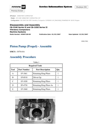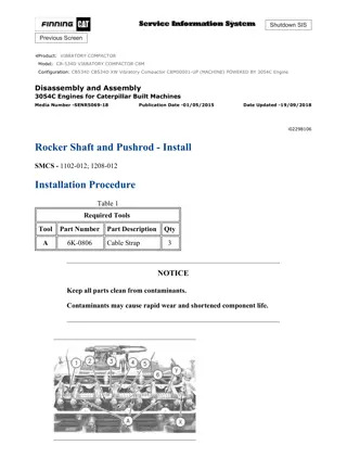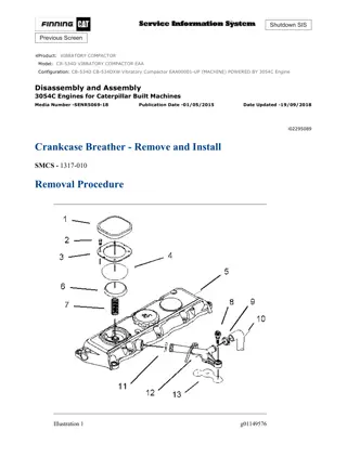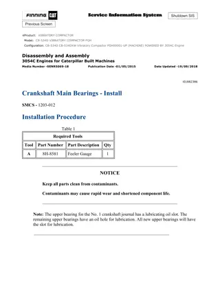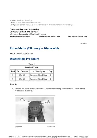
Caterpillar Cat CB-534D Vibratory Compactor (Prefix C4B) Service Repair Manual Instant Download
Please open the website below to get the complete manualnn//
Download Presentation

Please find below an Image/Link to download the presentation.
The content on the website is provided AS IS for your information and personal use only. It may not be sold, licensed, or shared on other websites without obtaining consent from the author. Download presentation by click this link. If you encounter any issues during the download, it is possible that the publisher has removed the file from their server.
E N D
Presentation Transcript
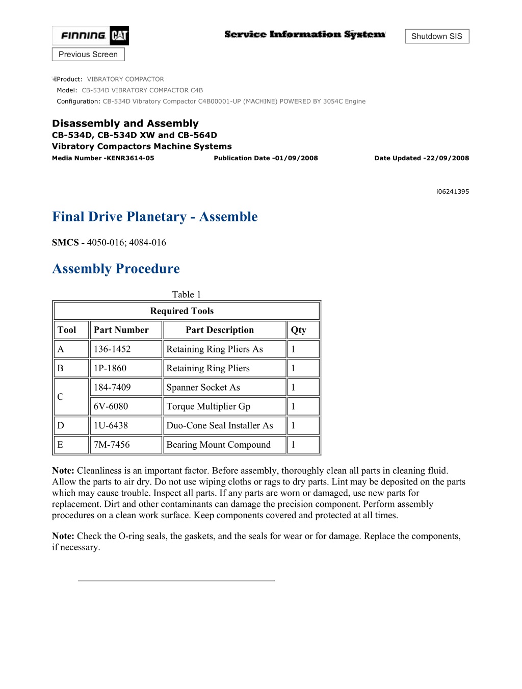
CB-534D Vibratory Compactor C4B00001-UP (MACHINE) POWERED BY 3054C ... 1/10 Shutdown SIS Previous Screen Product: VIBRATORY COMPACTOR Model: CB-534D VIBRATORY COMPACTOR C4B Configuration: CB-534D Vibratory Compactor C4B00001-UP (MACHINE) POWERED BY 3054C Engine Disassembly and Assembly CB-534D, CB-534D XW and CB-564D Vibratory Compactors Machine Systems Media Number -KENR3614-05 Publication Date -01/09/2008 Date Updated -22/09/2008 i06241395 Final Drive Planetary - Assemble SMCS - 4050-016; 4084-016 Assembly Procedure Table 1 Required Tools Tool Part Number Part Description Qty A 136-1452 Retaining Ring Pliers As 1 B 1P-1860 Retaining Ring Pliers 1 184-7409 Spanner Socket As 1 C 6V-6080 Torque Multiplier Gp 1 D 1U-6438 Duo-Cone Seal Installer As 1 E 7M-7456 Bearing Mount Compound 1 Note: Cleanliness is an important factor. Before assembly, thoroughly clean all parts in cleaning fluid. Allow the parts to air dry. Do not use wiping cloths or rags to dry parts. Lint may be deposited on the parts which may cause trouble. Inspect all parts. If any parts are worn or damaged, use new parts for replacement. Dirt and other contaminants can damage the precision component. Perform assembly procedures on a clean work surface. Keep components covered and protected at all times. Note: Check the O-ring seals, the gaskets, and the seals for wear or for damage. Replace the components, if necessary. https://127.0.0.1/sisweb/sisweb/techdoc/techdoc_print_page.jsp?returnurl=/sisw... 2021/5/3
CB-534D Vibratory Compactor C4B00001-UP (MACHINE) POWERED BY 3054C ... 2/10 Illustration 1 g01196353 1. Use Tooling (A) to install second half of Duo-Cone seal (35) . Refer to Disassembly and Assembly , "Duo-Cone Conventional Seals - Install". Illustration 2 g01196323 2. Install bearing cups (30) in rotating housing (28) . Illustration 3 g01196617 3. Install bearing cone (33) in rotating housing (28) . 4. Use Tooling (D) and install the first half of Duo-Cone seal (34) in rotating housing (28) . Refer to Disassembly and Assembly , "Duo-Cone Conventional Seal - Install". https://127.0.0.1/sisweb/sisweb/techdoc/techdoc_print_page.jsp?returnurl=/sisw... 2021/5/3
CB-534D Vibratory Compactor C4B00001-UP (MACHINE) POWERED BY 3054C ... 3/10 Illustration 4 g01196623 5. Install rotating housing (28) on hub (27) . Install shims (32) . Illustration 5 g01196628 6. Install spacer (31) . Illustration 6 g01196321 7. Install bearing cone (29) . https://127.0.0.1/sisweb/sisweb/techdoc/techdoc_print_page.jsp?returnurl=/sisw... 2021/5/3
https://www.ebooklibonline.com Hello dear friend! Thank you very much for reading. Enter the link into your browser. The full manual is available for immediate download. https://www.ebooklibonline.com
CB-534D Vibratory Compactor C4B00001-UP (MACHINE) POWERED BY 3054C ... 4/10 Illustration 7 g01196302 Illustration 8 g01196317 8. Apply Tooling (E) to ring nut (26) . Use Tooling (C) and tighten ring nut (26) to a torque of 1635 N m (1200 lb ft). Illustration 9 g01196184 9. Install planetary gears (25) . Use Tooling (B) to install retaining rings (24) . 10. Install O-ring seal (23) . https://127.0.0.1/sisweb/sisweb/techdoc/techdoc_print_page.jsp?returnurl=/sisw... 2021/5/3
CB-534D Vibratory Compactor C4B00001-UP (MACHINE) POWERED BY 3054C ... 5/10 Illustration 10 g01196225 11. Install ring gear (14) and output pinion (22) . Illustration 11 g01196161 12. Install needle bearings (21) , planetary gears (17) , and retaining washers (20) . Use Tooling (B) to install retaining rings (19) . Illustration 12 g01196151 13. Install planetary gears (17) and planetary carrier (18) as a unit. https://127.0.0.1/sisweb/sisweb/techdoc/techdoc_print_page.jsp?returnurl=/sisw... 2021/5/3
CB-534D Vibratory Compactor C4B00001-UP (MACHINE) POWERED BY 3054C ... 6/10 Illustration 13 g03868919 14. Install input shaft (16) .Install three bolts equally spaced to ensure that ring gear (14) is held to the housing with no gap. Illustration 14 g03868927 https://127.0.0.1/sisweb/sisweb/techdoc/techdoc_print_page.jsp?returnurl=/sisw... 2021/5/3
CB-534D Vibratory Compactor C4B00001-UP (MACHINE) POWERED BY 3054C ... 7/10 Illustration 15 g03868928 15. Use the following procedure in order to determine the correct amount of shims that are located under pad (13A) . a. Measure Dimension (A) . Dimension (A) is the distance between the mounting surface of cover (13) and the top of pad (13A) . b. Measure Dimension (B) . Dimension (B) is the distance between the mounting surface of ring gear (14) and the top of input shaft (16) . c. Find the clearance by subtracting Dimension (A) from Dimension (B) . The correct clearance is 0.50 0.20 mm (0.020 0.008 inch). Add shims (13B) or subtract shims (13B) in order to obtain the correct clearance. Illustration 16 g03868936 16. Install O-ring seal (15) on cover (13) . Install the shims and pad (13A) in cover (13) . Illustration 17 g01196134 17. Install cover (13) on ring gear (14) . Install bolts (12) . https://127.0.0.1/sisweb/sisweb/techdoc/techdoc_print_page.jsp?returnurl=/sisw... 2021/5/3
CB-534D Vibratory Compactor C4B00001-UP (MACHINE) POWERED BY 3054C ... 8/10 Illustration 18 g01196035 18. Install brake discs (10) and friction discs (11) . Illustration 19 g01196032 19. Install input coupling (9) , socket head screw (8) , O-ring seals (6) , backup rings (7) , and brake piston (5) . https://127.0.0.1/sisweb/sisweb/techdoc/techdoc_print_page.jsp?returnurl=/sisw... 2021/5/3
CB-534D Vibratory Compactor C4B00001-UP (MACHINE) POWERED BY 3054C ... 9/10 Illustration 20 g01195882 Illustration 21 g01196007 20. Install large springs (4) and small springs (3) in brake piston (5) . 21. Install retaining disc (2) . https://127.0.0.1/sisweb/sisweb/techdoc/techdoc_print_page.jsp?returnurl=/sisw... 2021/5/3
CB-534D Vibratory Compactor C4B00001-UP (MACHINE) POWERED BY 3054... 10/10 Illustration 22 g01195966 Personal injury can result from being struck by parts propelled by a released spring force. Make sure to wear all necessary protective equipment. Follow the recommended procedure and use all recommended tooling to release the spring force. 22. Place the planetary in a press. Put slight compression on retaining disc (2) with the press. Use Tooling (A) to install retaining ring (1) . Slowly release the spring compression. Copyright 1993 - 2021 Caterpillar Inc. Mon May 3 23:03:03 UTC+0800 2021 All Rights Reserved. Private Network For SIS Licensees. https://127.0.0.1/sisweb/sisweb/techdoc/techdoc_print_page.jsp?returnurl=/sisw... 2021/5/3
CB-534D Vibratory Compactor C4B00001-UP (MACHINE) POWERED BY 3054C ... 1/5 Shutdown SIS Previous Screen Product: VIBRATORY COMPACTOR Model: CB-534D VIBRATORY COMPACTOR C4B Configuration: CB-534D Vibratory Compactor C4B00001-UP (MACHINE) POWERED BY 3054C Engine Disassembly and Assembly CB-534D, CB-534D XW and CB-564D Vibratory Compactors Machine Systems Media Number -KENR3614-05 Publication Date -01/09/2008 Date Updated -22/09/2008 i03205830 Final Drive Planetary - Install SMCS - 4050-012; 4084-012 Installation Procedure Table 1 Required Tools Tool Part Number Part Description Qty A 180-3034 Repair Stand Set 1 B 232-0228 Lift Bracket 1 C 7X-2476 Bolt 2 Illustration 1 g01207550 1. Position plate (20) and install nuts (19) on final drive planetary (21) . https://127.0.0.1/sisweb/sisweb/techdoc/techdoc_print_page.jsp?returnurl=/sisw... 2021/5/3
CB-534D Vibratory Compactor C4B00001-UP (MACHINE) POWERED BY 3054C ... 2/5 Illustration 2 g01178821 2. Attach a suitable lifting device to support (18). Position support (18) on the final drive planetary. The weight of support (18) is approximately 145 kg (320 lb). Install bolts (17). Illustration 3 g01178794 3. Install propel motor (14) and bolts (16) to the final drive planetary. 4. Install hose assembly (15) . 5. Install bolts (13) and (12) . 6. Fill the final drive planetary with oil. Refer to the Operation and Maintenance Manual, "Drum Drive Planetary Oil - Change". https://127.0.0.1/sisweb/sisweb/techdoc/techdoc_print_page.jsp?returnurl=/sisw... 2021/5/3
CB-534D Vibratory Compactor C4B00001-UP (MACHINE) POWERED BY 3054C ... 3/5 Illustration 4 g01178598 Illustration 5 g01178725 7. Attach Tooling (B) and a suitable lifting device to final drive assembly (9) . 8. Tooling (C) must be modified in order to be used as a guide bolt. Position Tooling (C) in a suitable vise. Remove the head of the bolt in order to use Tooling (C) as a guide bolt. Install final drive assembly (9) on Tooling (C). The weight of final drive assembly (9) is approximately 370 kg (816 lb). 9. Install bolts (11) . 10. Remove Tooling (B), the suitable lifting device, and Tooling (C). Install bolts (10) to final drive assembly (9) . https://127.0.0.1/sisweb/sisweb/techdoc/techdoc_print_page.jsp?returnurl=/sisw... 2021/5/3
CB-534D Vibratory Compactor C4B00001-UP (MACHINE) POWERED BY 3054C ... 4/5 Illustration 6 g01178031 11. Raise the machine until the drum rises off the ground. Remove Tooling (A) . Illustration 7 g01177986 12. Connect harness assemblies (7) and (8). Install the cable straps. 13. Connect hose assemblies (6) . Illustration 8 g01178006 https://127.0.0.1/sisweb/sisweb/techdoc/techdoc_print_page.jsp?returnurl=/sisw... 2021/5/3
CB-534D Vibratory Compactor C4B00001-UP (MACHINE) POWERED BY 3054C ... 5/5 14. Connect hose assemblies (5) . Illustration 9 g01177927 15. Position cover (3) and bolts (4). this procedure applies to CB-534DXW machines only. Illustration 10 g01177884 16. Position cover (2) and bolts (1) . Copyright 1993 - 2021 Caterpillar Inc. Mon May 3 23:03:59 UTC+0800 2021 All Rights Reserved. Private Network For SIS Licensees. https://127.0.0.1/sisweb/sisweb/techdoc/techdoc_print_page.jsp?returnurl=/sisw... 2021/5/3
CB-534D Vibratory Compactor C4B00001-UP (MACHINE) POWERED BY 3054C ... 1/5 Shutdown SIS Previous Screen Product: VIBRATORY COMPACTOR Model: CB-534D VIBRATORY COMPACTOR C4B Configuration: CB-534D Vibratory Compactor C4B00001-UP (MACHINE) POWERED BY 3054C Engine Disassembly and Assembly CB-534D, CB-534D XW and CB-564D Vibratory Compactors Machine Systems Media Number -KENR3614-05 Publication Date -01/09/2008 Date Updated -22/09/2008 i02438107 Articulating Hitch - Remove SMCS - 7057-011 Removal Procedure Table 1 Required Tools Tool Part Number Part Description Qty A 180-3032 Repair Stand Set 1 B 140-7742 Sleeve 2 C 1U-8230 Nylon Sling 2 D 1U-9744 Hydraulic Jack 1 Start By: A. Remove the engine enclosure. Refer to Disassembly and Assembly, "Engine Enclosure - Remove and Install". https://127.0.0.1/sisweb/sisweb/techdoc/techdoc_print_page.jsp?returnurl=/sisw... 2021/5/3
CB-534D Vibratory Compactor C4B00001-UP (MACHINE) POWERED BY 3054C ... 2/5 Illustration 1 g01095895 1. Raise the front of the machine and install Tooling (A) . Illustration 2 g01218305 2. Remove bolt (1) and pin assembly (2). Remove steering cylinder (4) from articulating hitch (3) . https://127.0.0.1/sisweb/sisweb/techdoc/techdoc_print_page.jsp?returnurl=/sisw... 2021/5/3
CB-534D Vibratory Compactor C4B00001-UP (MACHINE) POWERED BY 3054C ... 3/5 Illustration 3 g01095928 A typical example 3. Attach a suitable lifting device, Tooling (B), and Tooling (C) to the rear frame. Illustration 4 g01218296 4. Secure Tooling (D) to articulating hitch (3). Remove bolts (6) from each side of the front frame. 5. Remove bolts (5) from the rear frame. Lift the rear frame and move the rear frame far enough in order to provide clearance for articulating hitch (3). The weight of articulating hitch (3) is approximately 265 kg (585 lb). https://127.0.0.1/sisweb/sisweb/techdoc/techdoc_print_page.jsp?returnurl=/sisw... 2021/5/3
CB-534D Vibratory Compactor C4B00001-UP (MACHINE) POWERED BY 3054C ... 4/5 Illustration 5 g01218342 6. Remove bolts (7), upper cap (8), and plug (9) . Illustration 6 g01218354 7. Remove shims (10) and shaft (11) . Illustration 7 g01218493 8. Remove bolts (12), lower cap (13), and plug (14) . https://127.0.0.1/sisweb/sisweb/techdoc/techdoc_print_page.jsp?returnurl=/sisw... 2021/5/3
CB-534D Vibratory Compactor C4B00001-UP (MACHINE) POWERED BY 3054C ... 5/5 Illustration 8 g01218506 9. Remove lip seal (15) and bearing cone (16) from the upper and lower caps. Illustration 9 g01218522 10. If necessary, remove bearing cup (17) from the upper and lower caps. Copyright 1993 - 2021 Caterpillar Inc. Mon May 3 23:04:55 UTC+0800 2021 All Rights Reserved. Private Network For SIS Licensees. https://127.0.0.1/sisweb/sisweb/techdoc/techdoc_print_page.jsp?returnurl=/sisw... 2021/5/3
CB-534D Vibratory Compactor C4B00001-UP (MACHINE) POWERED BY 3054C ... 1/7 Shutdown SIS Previous Screen Product: VIBRATORY COMPACTOR Model: CB-534D VIBRATORY COMPACTOR C4B Configuration: CB-534D Vibratory Compactor C4B00001-UP (MACHINE) POWERED BY 3054C Engine Disassembly and Assembly CB-534D, CB-534D XW and CB-564D Vibratory Compactors Machine Systems Media Number -KENR3614-05 Publication Date -01/09/2008 Date Updated -22/09/2008 i03515081 Articulating Hitch - Install SMCS - 7057-012 Installation Procedure Table 1 Required Tools Tool Part Number Part Description Qty A 180-3032 Repair Stand Set 1 B 140-7742 Sleeve 2 C 1U-8230 Nylon Sling 2 D 1U-9744 Hydraulic Jack 1 E 1P-0808 Multipurpose Grease 1 F 6V-4876 Lubricant 1 G 3B-8489 Grease Fitting 2 https://127.0.0.1/sisweb/sisweb/techdoc/techdoc_print_page.jsp?returnurl=/sisw... 2021/5/3
CB-534D Vibratory Compactor C4B00001-UP (MACHINE) POWERED BY 3054C ... 2/7 Illustration 1 g01218522 1. Install bearing cup (17) in the upper and lower caps. Illustration 2 g01218506 2. Install bearing cone (16) and lip seal (15) in the upper and lower caps. Illustration 3 g01099053 https://127.0.0.1/sisweb/sisweb/techdoc/techdoc_print_page.jsp?returnurl=/sisw... 2021/5/3
CB-534D Vibratory Compactor C4B00001-UP (MACHINE) POWERED BY 3054C ... 3/7 3. Use a digital caliper to measure the distance between the ears on the pin end of the hitch. Measure the right and left side of the counterbores. Take the average of the two measurements in order to get Dimension (X) . Subtract Dimension (X) from 250 mm (9.8 inch). This will be the required shim thickness. This shim thickness will achieve the required preload. Install shims. Illustration 4 g01218493 4. Install lower cap (13) , plug (14) , and bolts (12) . Illustration 5 g01218872 5. Apply Tooling (F) to shaft (11) , as shown. https://127.0.0.1/sisweb/sisweb/techdoc/techdoc_print_page.jsp?returnurl=/sisw... 2021/5/3
CB-534D Vibratory Compactor C4B00001-UP (MACHINE) POWERED BY 3054C ... 4/7 Illustration 6 g01218354 6. Install shaft (11) and position shims (10) . Illustration 7 g01218342 7. Install upper cap (8) , plug (9) , and bolts (7) . Tighten bolts (7) to a torque of 102 N m (75 lb ft). Illustration 8 g01218878 https://127.0.0.1/sisweb/sisweb/techdoc/techdoc_print_page.jsp?returnurl=/sisw... 2021/5/3
CB-534D Vibratory Compactor C4B00001-UP (MACHINE) POWERED BY 3054C ... 5/7 8. Remove plugs (9) and (14) from the upper and lower caps. Install Tooling (G) . Fill the caps with Tooling (F) . Remove Tooling (G) and install plugs (9) and (14) . 9. Repeat Steps 1 through 8 for the other end of the hitch assembly. Illustration 9 g01095928 A typical example 10. Attach a suitable lifting device, Tooling (B) and Tooling (C) to the rear frame. Illustration 10 g01218296 11. Secure Tooling (D) to articulating hitch (3) . Install articulating hitch (3) in the machine. The weight of articulating hitch (3) is approximately 265 kg (585 lb). https://127.0.0.1/sisweb/sisweb/techdoc/techdoc_print_page.jsp?returnurl=/sisw... 2021/5/3
Suggest: If the above button click is invalid. Please download this document first, and then click the above link to download the complete manual. Thank you so much for reading
CB-534D Vibratory Compactor C4B00001-UP (MACHINE) POWERED BY 3054C ... 6/7 12. Install bolts (6) in each side of the rear frame. Install articulating hitch (3) in the machine. Tighten all bolts (6) evenly in order to keep an even gap on the right and left side of articulating hitch (3) . A gap will exist on each side of articulating hitch (3) . 13. Install bolts (5) in the front frame. Repeat Step 12. 14. Remove the suitable lifting device. Tooling (B) , Tooling (C) , and Tooling (D) from the rear frame. Illustration 11 g01218305 15. Install steering cylinder (4) to articulating hitch assembly (3) . Install pin assembly (2) and bolt (1) . Illustration 12 g01095895 16. Raise the front of the machine and install Tooling (A) . End By: Install the engine enclosure. Refer to Disassembly and Assembly, "Engine Enclosure - Remove and Install". Copyright 1993 - 2021 Caterpillar Inc. Mon May 3 23:05:50 UTC+0800 2021 All Rights Reserved. https://127.0.0.1/sisweb/sisweb/techdoc/techdoc_print_page.jsp?returnurl=/sisw... 2021/5/3
CB-534D Vibratory Compactor C4B00001-UP (MACHINE) POWERED BY 3054C ... 7/7 Private Network For SIS Licensees. https://127.0.0.1/sisweb/sisweb/techdoc/techdoc_print_page.jsp?returnurl=/sisw... 2021/5/3
https://www.ebooklibonline.com Hello dear friend! Thank you very much for reading. Enter the link into your browser. The full manual is available for immediate download. https://www.ebooklibonline.com

