Caterpillar Cat CB-534B Vibratory Compactor (Prefix 5RN) Service Repair Manual Instant Download
Please open the website below to get the complete manualnn//
Download Presentation

Please find below an Image/Link to download the presentation.
The content on the website is provided AS IS for your information and personal use only. It may not be sold, licensed, or shared on other websites without obtaining consent from the author. Download presentation by click this link. If you encounter any issues during the download, it is possible that the publisher has removed the file from their server.
E N D
Presentation Transcript
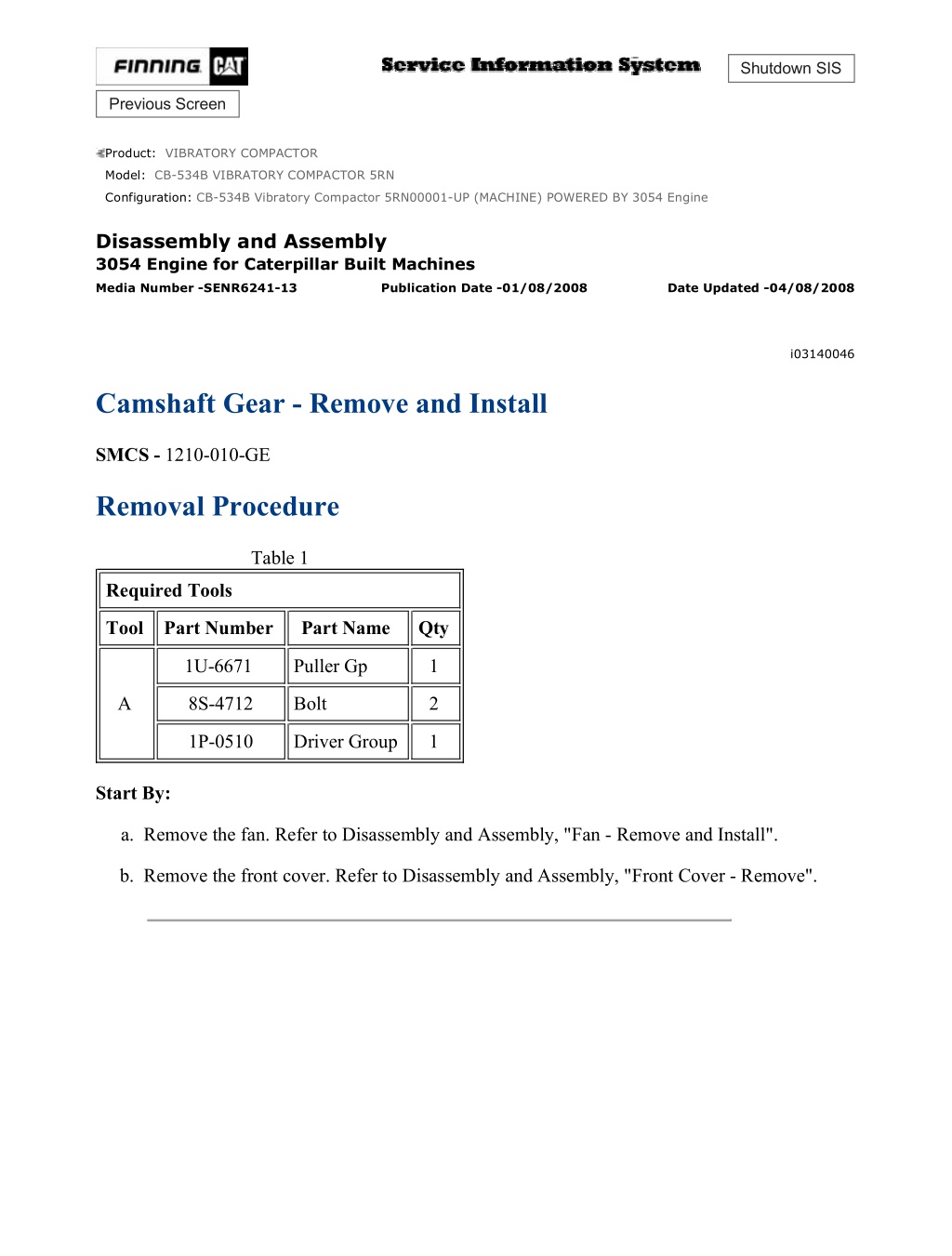
CB-534B Vibratory Compactor 5RN00001-UP (MACHINE) POWERED BY 3054 En... 1/4 Shutdown SIS Previous Screen Product: VIBRATORY COMPACTOR Model: CB-534B VIBRATORY COMPACTOR 5RN Configuration: CB-534B Vibratory Compactor 5RN00001-UP (MACHINE) POWERED BY 3054 Engine Disassembly and Assembly 3054 Engine for Caterpillar Built Machines Media Number -SENR6241-13 Publication Date -01/08/2008 Date Updated -04/08/2008 i03140046 Camshaft Gear - Remove and Install SMCS - 1210-010-GE Removal Procedure Table 1 Required Tools Tool Part Number Part Name Qty 1U-6671 Puller Gp 1 A 8S-4712 Bolt 2 1P-0510 Driver Group 1 Start By: a. Remove the fan. Refer to Disassembly and Assembly, "Fan - Remove and Install". b. Remove the front cover. Refer to Disassembly and Assembly, "Front Cover - Remove". https://127.0.0.1/sisweb/sisweb/techdoc/techdoc_print_page.jsp?returnurl=/sis... 2021/5/10
CB-534B Vibratory Compactor 5RN00001-UP (MACHINE) POWERED BY 3054 En... 2/4 Illustration 1 g00541128 1. Rotate the crankshaft until the timing marks on the crankshaft gear, the camshaft gear, and the fuel injection pump gear are aligned, as shown. Note: The timing marks on the idler gear may not be aligned. This is caused by the difference in the speed of the rotation of the idler gear. Illustration 2 g00541130 2. Remove bolt (1) and the washer from the camshaft gear (2). https://127.0.0.1/sisweb/sisweb/techdoc/techdoc_print_page.jsp?returnurl=/sis... 2021/5/10
CB-534B Vibratory Compactor 5RN00001-UP (MACHINE) POWERED BY 3054 En... 3/4 Illustration 3 g00541131 3. Install Tooling (A) and remove camshaft gear. Note: Do not lose the key from the camshaft gear. 4. Inspect the camshaft gear for wear and damage. Replace the gear, if necessary. Installation Procedure Illustration 4 g00541130 1. Install camshaft gear (2) in the front housing. Note: When you install the camshaft gear, ensure that the teeth that have the timing marks are facing toward the front. Also, ensure that the key is aligned properly in the keyway. If necessary, tap the gear with a soft hammer in order to seat the key in the keyway. 2. If necessary, remove the idler gear in order to align the gear teeth correctly. 3. Install the washer and bolt (1) on the camshaft gear. Tighten bolt (1) to a torque of 95 N m (70 lb ft). Note: Ensure that the timing marks on the camshaft gear, the crankshaft gear, and the fuel injection pump gear are aligned. https://127.0.0.1/sisweb/sisweb/techdoc/techdoc_print_page.jsp?returnurl=/sis... 2021/5/10
https://www.ebooklibonline.com Hello dear friend! Thank you very much for reading. Enter the link into your browser. The full manual is available for immediate download. https://www.ebooklibonline.com
CB-534B Vibratory Compactor 5RN00001-UP (MACHINE) POWERED BY 3054 En... 4/4 4. If a new camshaft gear is used, check the backlash of the camshaft gear. The minimum backlash for a new gear is 0.08 mm (0.003 inch). End By: a. Install the front cover. Refer to Disassembly and Assembly, "Front Cover - Install". b. Install the fan. Refer to Disassembly and Assembly, "Fan - Remove and Install". Copyright 1993 - 2021 Caterpillar Inc. Mon May 10 23:01:06 UTC+0800 2021 All Rights Reserved. Private Network For SIS Licensees. https://127.0.0.1/sisweb/sisweb/techdoc/techdoc_print_page.jsp?returnurl=/sis... 2021/5/10
CB-534B Vibratory Compactor 5RN00001-UP (MACHINE) POWERED BY 3054 En... 1/3 Shutdown SIS Previous Screen Product: VIBRATORY COMPACTOR Model: CB-534B VIBRATORY COMPACTOR 5RN Configuration: CB-534B Vibratory Compactor 5RN00001-UP (MACHINE) POWERED BY 3054 Engine Disassembly and Assembly 3054 Engine for Caterpillar Built Machines Media Number -SENR6241-13 Publication Date -01/08/2008 Date Updated -04/08/2008 i06043534 Camshaft Bearings - Remove and Install SMCS - 1211-010 Removal Procedure Table 1 Required Tools Tool Part Number Part Description Qty 8S-2241 Camshaft Bearing Tool Group 1 A 8H-0684 Ratchet Wrench 1 Start By: A. If the engine is equipped with a balancer, remove the balancer. Refer to Disassembly and Assembly, "Balancer - Remove". If the engine is not equipped with a balancer, remove the engine oil pump. Refer to Disassembly and Assembly, "Engine Oil Pump - Remove" for the correct procedure. B. Remove the camshaft. Refer to Disassembly and Assembly, "Camshaft - Remove and Install" for the correct procedure. NOTICE Keep all parts clean from contaminants. Contaminants may cause rapid wear and shortened component life. https://127.0.0.1/sisweb/sisweb/techdoc/techdoc_print_page.jsp?returnurl=/sis... 2021/5/10
CB-534B Vibratory Compactor 5RN00001-UP (MACHINE) POWERED BY 3054 En... 2/3 Illustration 1 g01270437 1. Inspect camshaft bearing (1) . Refer to Specifications, "Camshaft Bearings" for more information. 2. For worn or damaged camshaft bearing (1) use Tooling (A) in order to remove the camshaft bearing from the cylinder block. Note: Remove the camshaft bearing from the front of the cylinder block. Installation Procedure Table 2 Required Tools Tool Part Number Part Description Qty 8S-2241 Camshaft Bearing Tool Group 1 A 8H-0684 Ratchet Wrench 1 NOTICE Keep all parts clean from contaminants. Contaminants may cause rapid wear and shortened component life. 1. Clean the bearing housing in the cylinder block. Ensure that the oil holes in the bearing housing are free from debris. https://127.0.0.1/sisweb/sisweb/techdoc/techdoc_print_page.jsp?returnurl=/sis... 2021/5/10
CB-534B Vibratory Compactor 5RN00001-UP (MACHINE) POWERED BY 3054 En... 3/3 Illustration 2 g01266512 2. Lubricate the bearing housing in the cylinder block with clean engine oil. 3. Accurately align two Oil Holes (X) in camshaft bearing (1) with the two oil holes in the cylinder block. Note: Groove (Y) in the camshaft bearing must be to the top of the cylinder block. 4. Use Tooling (A) in order to install camshaft bearing (1) into the cylinder block. Install the camshaft bearing so that the front edge of the bearing is flush with the face of the recess in the cylinder block. Note: Ensure that all oil holes are correctly aligned. If the oils are not correctly aligned, the camshaft bearing should be removed. End By: a. Install the camshaft. Refer to Disassembly and Assembly, "Camshaft - Remove and Install" for the correct procedure. b. If the engine is equipped with a balancer, install the balancer. Refer to Disassembly and Assembly, "Balancer - Install". If the engine is not equipped with a balancer, install the engine oil pump. Refer to Disassembly and Assembly, "Engine Oil Pump - Install" for the correct procedure. Copyright 1993 - 2021 Caterpillar Inc. Mon May 10 23:02:02 UTC+0800 2021 All Rights Reserved. Private Network For SIS Licensees. https://127.0.0.1/sisweb/sisweb/techdoc/techdoc_print_page.jsp?returnurl=/sis... 2021/5/10
CB-534B Vibratory Compactor 5RN00001-UP (MACHINE) POWERED BY 3054 En... 1/6 Shutdown SIS Previous Screen Product: VIBRATORY COMPACTOR Model: CB-534B VIBRATORY COMPACTOR 5RN Configuration: CB-534B Vibratory Compactor 5RN00001-UP (MACHINE) POWERED BY 3054 Engine Disassembly and Assembly 3054 Engine for Caterpillar Built Machines Media Number -SENR6241-13 Publication Date -01/08/2008 Date Updated -04/08/2008 i02974660 Engine Oil Pan - Remove and Install SMCS - 1302-010 Removal Procedure NOTICE Keep all parts clean from contaminants. Contaminants may cause rapid wear and shortened component life. NOTICE Care must be taken to ensure that fluids are contained during performance of inspection, maintenance, testing, adjusting and repair of the product. Be prepared to collect the fluid with suitable containers before opening any compartment or disassembling any component containing fluids. Refer to Special Publication, NENG2500, "Caterpillar Dealer Service Tool Catalog" for tools and supplies suitable to collect and contain fluids on Caterpillar products. Dispose of all fluids according to local regulations and mandates. https://127.0.0.1/sisweb/sisweb/techdoc/techdoc_print_page.jsp?returnurl=/sis... 2021/5/10
CB-534B Vibratory Compactor 5RN00001-UP (MACHINE) POWERED BY 3054 En... 2/6 Illustration 1 g01870497 Typical Example https://127.0.0.1/sisweb/sisweb/techdoc/techdoc_print_page.jsp?returnurl=/sis... 2021/5/10
CB-534B Vibratory Compactor 5RN00001-UP (MACHINE) POWERED BY 3054 En... 3/6 Illustration 2 g01871553 Note: The engine may be equipped with an oil drain plug or the engine may be equipped with a drain valve. 1. If equipped, remove drain plug (2) and the O-ring seal. If equipped, open drain valve (5) by turning handle (6) counterclockwise. Drain the engine oil into a suitable container for storage or disposal. 2. If necessary, remove drain valve (5) from adapter (7) . If necessary, remove adapter (7) from engine oil pan (3) . Note: In order to remove a oil pan, the engine must be removed from the machine. 3. Remove bolts (1) from engine oil pan (3) . 4. Remove engine oil pan (3) and gasket (4) . Installation Procedure NOTICE Keep all parts clean from contaminants. Contaminants may cause rapid wear and shortened component life. https://127.0.0.1/sisweb/sisweb/techdoc/techdoc_print_page.jsp?returnurl=/sis... 2021/5/10
CB-534B Vibratory Compactor 5RN00001-UP (MACHINE) POWERED BY 3054 En... 4/6 1. Clean the gasket surfaces of the cylinder block and the engine oil pan thoroughly. Illustration 3 g01870497 Typical Example https://127.0.0.1/sisweb/sisweb/techdoc/techdoc_print_page.jsp?returnurl=/sis... 2021/5/10
CB-534B Vibratory Compactor 5RN00001-UP (MACHINE) POWERED BY 3054 En... 5/6 Illustration 4 g01871553 2. Install a new gasket (4) to the cylinder block. Install engine oil pan (3) . 3. Install bolts (1) . Tighten bolts to a torque of 22 N m (16 lb ft). Note: The engine may be equipped with an oil drain plug or the engine may be equipped with a drain valve. 4. If drain valve (5) and adapter (7) were removed, use the following procedure. a. Install a new O-ring to the adapter (7) . b. Install adapter (7) into engine oil pan (3) . Tighten the adapter to a torque of 34 N m (25 lb ft). c. Install a new O-ring to drain valve (5) . d. Install drain valve (5) into adapter (7) . Tighten the drain valve to a torque of 34 N m (25 lb ft). 5. If equipped, install a new O-ring seal on drain plug (2) . Install the drain plug. Tighten the drain plug to a torque of 34 N m (25 lb ft). If equipped, close drain valve (5) by turning handle (6) clockwise. Turn handle (6) until the handle is tight. Do not overtighten the handle. 6. Fill the engine oil pan to the correct level that is indicated on the engine oil level gauge. https://127.0.0.1/sisweb/sisweb/techdoc/techdoc_print_page.jsp?returnurl=/sis... 2021/5/10
CB-534B Vibratory Compactor 5RN00001-UP (MACHINE) POWERED BY 3054 En... 6/6 Note: Refer to the Operation and Maintenance Manual, "Refill Capacities" for the correct engine oil capacity. Copyright 1993 - 2021 Caterpillar Inc. Mon May 10 23:02:58 UTC+0800 2021 All Rights Reserved. Private Network For SIS Licensees. https://127.0.0.1/sisweb/sisweb/techdoc/techdoc_print_page.jsp?returnurl=/sis... 2021/5/10
CB-534B Vibratory Compactor 5RN00001-UP (MACHINE) POWERED BY 3054 En... 1/2 Shutdown SIS Previous Screen Product: VIBRATORY COMPACTOR Model: CB-534B VIBRATORY COMPACTOR 5RN Configuration: CB-534B Vibratory Compactor 5RN00001-UP (MACHINE) POWERED BY 3054 Engine Disassembly and Assembly 3054 Engine for Caterpillar Built Machines Media Number -SENR6241-13 Publication Date -01/08/2008 Date Updated -04/08/2008 i04368112 Cylinder Liner - Remove SMCS - 1216-011 Removal Procedure Table 1 Required Tools Tool Part Number Part Description Qty 1A-1460 Bolt 3 2J-3507 Full Nut 1 5F-7347 Head 1 5H-1504 Hard Washer 1 5P-8245 Washer 3 A 6V-2183 Screw 1 8H-0684 Ratchet Wrench 1 9U-6234 Puller Plate 1 9U-6281 Leg 3 1D-5119 Nut 1 Start By: A. Remove the cylinder head. Refer to Disassembly and Assembly, "Cylinder Head - Remove". B. Remove the pistons and connecting rods. Refer to Disassembly and Assembly, "Pistons and Connecting Rods - Remove". https://127.0.0.1/sisweb/sisweb/techdoc/techdoc_print_page.jsp?returnurl=/sis... 2021/5/10
CB-534B Vibratory Compactor 5RN00001-UP (MACHINE) POWERED BY 3054 En... 2/2 C. Remove the piston cooling jets. Refer to Disassembly and Assembly, "Piston Cooling Jets - Remove and Install". NOTICE Keep all parts clean from contaminants. Contaminants may cause rapid wear and shortened component life. Note: Before you proceed with the removal of the cylinder liner, check the cylinder liners for wear or for damage. Check the inner diameter of each cylinder liner at the top, the middle, and the bottom. Check the inner diameter at two places that are 180 degrees away from each other. The maximum wear for the cylinder liners is 0.25 mm (.010 inch). Note: An engine may have a high rate of oil consumption if the surface of the cylinder liners are glazed. Glaze can be removed from the cylinder liners by honing the bore of the cylinder liner. 1. Rotate the crankshaft in order to gain access to the cylinder liner. Place a protective cover on the crankshaft in order to prevent damage. Illustration 1 g00893799 2. Install Tooling (A) . 3. Remove cylinder liner (1) . Copyright 1993 - 2021 Caterpillar Inc. Mon May 10 23:03:53 UTC+0800 2021 All Rights Reserved. Private Network For SIS Licensees. https://127.0.0.1/sisweb/sisweb/techdoc/techdoc_print_page.jsp?returnurl=/sis... 2021/5/10
CB-534B Vibratory Compactor 5RN00001-UP (MACHINE) POWERED BY 3054 En... 1/3 Shutdown SIS Previous Screen Product: VIBRATORY COMPACTOR Model: CB-534B VIBRATORY COMPACTOR 5RN Configuration: CB-534B Vibratory Compactor 5RN00001-UP (MACHINE) POWERED BY 3054 Engine Disassembly and Assembly 3054 Engine for Caterpillar Built Machines Media Number -SENR6241-13 Publication Date -01/08/2008 Date Updated -04/08/2008 i01746068 Cylinder Liner - Install SMCS - 1216-012 Installation Procedure Table 1 Required Tools Tool Part Number Part Description Qty 1A-1460 Bolt 3 2J-3507 Full Nut 1 5F-7347 Head 1 5H-1504 Hard Washer 1 A 5P-8245 Washer 1 6V-2183 Screw 1 8H-0684 Ratchet Wrench 1 9U-6235 Puller Plate 1 1U-9895 Cross Block 1 B 8T-0455 Liner Projection Tool Group 1 NOTICE Keep all parts clean from contaminants. Contaminants may cause rapid wear and shortened component life. https://127.0.0.1/sisweb/sisweb/techdoc/techdoc_print_page.jsp?returnurl=/sis... 2021/5/10
CB-534B Vibratory Compactor 5RN00001-UP (MACHINE) POWERED BY 3054 En... 2/3 1. Clean the cylinder block bore with 8T-9011 Component Cleaner before you install the cylinder liner. 2. Apply clean engine oil to the cylinder block bore. Do not apply the clean engine oil to the top 50.0 mm (2.00 inch) of the cylinder block bore. Illustration 1 g00635369 3. Install Tooling (A). 4. Install cylinder liner (1). 5. Press cylinder liner (1) into the cylinder block within 50.0 mm (2.00 inch) of the top of the cylinder block. Note: Cylinder liner (1) is a press fit to a distance of 0.03 mm ( 0.001 inch) from the top of the cylinder block. 6. Apply 6V-1541 Quick Cure Primer to the exposed area of cylinder liner (1). Also apply 9S- 3265 Compound to the exposed area of cylinder liner (1). 7. Wipe off any excess compound from cylinder liner (1). https://127.0.0.1/sisweb/sisweb/techdoc/techdoc_print_page.jsp?returnurl=/sis... 2021/5/10
CB-534B Vibratory Compactor 5RN00001-UP (MACHINE) POWERED BY 3054 En... 3/3 Illustration 2 g00635363 8. Use Tooling (B) to check that cylinder liner (1) is 0.10 mm (0.004 inch) above the cylinder block or below the cylinder block. 9. Immediately after you install a new cylinder liner, follow the recommendations below: a. Do not operate the engine at full load. b. Do not operate the engine at high speed. c. Do not allow the engine to run at low idle for an extended period of time. End By: a. Install the piston cooling jets. Refer to Disassembly and Assembly, "Piston Cooling Jets - Install". b. Install the pistons and connecting rods. Refer to Disassembly and Assembly, "Piston and Connecting Rods - Install". c. Install the cylinder head. Refer to Disassembly and Assembly, "Cylinder Head - Install". Copyright 1993 - 2021 Caterpillar Inc. Mon May 10 23:04:49 UTC+0800 2021 All Rights Reserved. Private Network For SIS Licensees. https://127.0.0.1/sisweb/sisweb/techdoc/techdoc_print_page.jsp?returnurl=/sis... 2021/5/10
CB-534B Vibratory Compactor 5RN00001-UP (MACHINE) POWERED BY 3054 En... 1/4 Shutdown SIS Previous Screen Product: VIBRATORY COMPACTOR Model: CB-534B VIBRATORY COMPACTOR 5RN Configuration: CB-534B Vibratory Compactor 5RN00001-UP (MACHINE) POWERED BY 3054 Engine Disassembly and Assembly 3054 Engine for Caterpillar Built Machines Media Number -SENR6241-13 Publication Date -01/08/2008 Date Updated -04/08/2008 i01548436 Piston Cooling Jets - Remove and Install SMCS - 1331-010 Removal Procedure Start By: a. Remove the engine oil pan. Refer to Disassembly and Assembly, "Engine Oil Pan - Remove and Install". NOTICE Keep all parts clean from contaminants. Contaminants may cause rapid wear and shortened component life. NOTICE Care must be taken to ensure that fluids are contained during performance of inspection, maintenance, testing, adjusting and repair of the product. Be prepared to collect the fluid with suitable containers before opening any compartment or disassembling any component containing fluids. Refer to Special Publication, NENG2500, "Caterpillar Dealer Service Tool Catalog" for tools and supplies suitable to collect and contain fluids on Caterpillar products. Dispose of all fluids according to local regulations and mandates. https://127.0.0.1/sisweb/sisweb/techdoc/techdoc_print_page.jsp?returnurl=/sis... 2021/5/10
CB-534B Vibratory Compactor 5RN00001-UP (MACHINE) POWERED BY 3054 En... 2/4 Note: The naturally aspirated 3054 marine engine has one piston cooling jet that is located inside the number one cylinder. The naturally aspirated 3056 marine engine is not equipped with piston cooling jets. Illustration 1 g00548374 Illustration 2 g00606467 1. Remove valve assembly (1) from piston cooling jet (2). 2. Remove piston cooling jet (2) from the cylinder block. Note: The engine crankshaft may be rotated in order to access all of the piston cooling jets. Note: Ensure that the ball moves freely within the valve assembly of the piston cooling jet. Check that the tube of the piston cooling jet is not damaged. 3. Remove hollow dowel (3) from the cylinder block. Note: Hollow dowel (3) is used to locate the piston cooling jet. https://127.0.0.1/sisweb/sisweb/techdoc/techdoc_print_page.jsp?returnurl=/sis... 2021/5/10
CB-534B Vibratory Compactor 5RN00001-UP (MACHINE) POWERED BY 3054 En... 3/4 4. Repeat Steps 1 through 3 for the removal of the remaining piston cooling jets. Installation Procedure NOTICE Keep all parts clean from contaminants. Contaminants may cause rapid wear and shortened component life. Illustration 3 g00548374 Illustration 4 g00606467 1. Install piston cooling jet (2) to the cylinder block. https://127.0.0.1/sisweb/sisweb/techdoc/techdoc_print_page.jsp?returnurl=/sis... 2021/5/10
CB-534B Vibratory Compactor 5RN00001-UP (MACHINE) POWERED BY 3054 En... 4/4 Note: Ensure that piston cooling jet (2) is properly located on hollow dowel (3). Refer to the Specifications Manual, "Piston Cooling Jet" for the correct procedure for the alignment of the piston cooling jet. 2. Install valve assembly (1) into the piston cooling jet (2). Tighten the banjo bolt of the valve assembly (1) to a torque of 20 N m (15 lb ft). 3. Repeat Steps 1 through 2 for the installation of the remaining piston cooling jets. End By: a. Install the engine oil pan. Refer to Disassembly and Assembly, "Engine Oil Pan - Remove and Install". Copyright 1993 - 2021 Caterpillar Inc. Mon May 10 23:05:45 UTC+0800 2021 All Rights Reserved. Private Network For SIS Licensees. https://127.0.0.1/sisweb/sisweb/techdoc/techdoc_print_page.jsp?returnurl=/sis... 2021/5/10
CB-534B Vibratory Compactor 5RN00001-UP (MACHINE) POWERED BY 3054 En... 1/2 Shutdown SIS Previous Screen Product: VIBRATORY COMPACTOR Model: CB-534B VIBRATORY COMPACTOR 5RN Configuration: CB-534B Vibratory Compactor 5RN00001-UP (MACHINE) POWERED BY 3054 Engine Disassembly and Assembly 3054 Engine for Caterpillar Built Machines Media Number -SENR6241-13 Publication Date -01/08/2008 Date Updated -04/08/2008 i02453078 Pistons and Connecting Rods - Remove SMCS - 1225-011 Removal Procedure Table 1 Required Tools Tool Part Number Part Description Qty A 8S-2269 Ridge Reamer 1 Start By: A. Remove the cylinder head. Refer to Disassembly and Assembly, "Cylinder Head - Remove". B. Remove the engine oil pump. Refer to Disassembly and Assembly, "Engine Oil Pump - Remove". C. Remove the piston cooling jets. Refer to Disassembly and Assembly, "Piston Cooling Jets - Remove and Install". NOTICE Keep all parts clean from contaminants. Contaminants may cause rapid wear and shortened component life. 1. Use Tooling (A) to remove the liner wear ridge from the inner surface of the cylinder liner. 2. Position the two pistons that are being removed at the bottom center position. https://127.0.0.1/sisweb/sisweb/techdoc/techdoc_print_page.jsp?returnurl=/sis... 2021/5/10
CB-534B Vibratory Compactor 5RN00001-UP (MACHINE) POWERED BY 3054 En... 2/2 Illustration 1 g00550548 3. Remove nuts (1) and the bolts. 4. Remove connecting rod caps (2) and the connecting rod bearings. Keep connecting rod caps (2) and the connecting rod bearings together for installation. Illustration 2 g00550549 5. Push pistons (3) and the connecting rods out of the top of cylinder block (4) . Copyright 1993 - 2021 Caterpillar Inc. Mon May 10 23:06:41 UTC+0800 2021 All Rights Reserved. Private Network For SIS Licensees. https://127.0.0.1/sisweb/sisweb/techdoc/techdoc_print_page.jsp?returnurl=/sis... 2021/5/10
CB-534B Vibratory Compactor 5RN00001-UP (MACHINE) POWERED BY 3054 En... 1/3 Shutdown SIS Previous Screen Product: VIBRATORY COMPACTOR Model: CB-534B VIBRATORY COMPACTOR 5RN Configuration: CB-534B Vibratory Compactor 5RN00001-UP (MACHINE) POWERED BY 3054 Engine Disassembly and Assembly 3054 Engine for Caterpillar Built Machines Media Number -SENR6241-13 Publication Date -01/08/2008 Date Updated -04/08/2008 i02088687 Pistons and Connecting Rods - Disassemble SMCS - 1225-015 Disassembly Procedure Table 1 Required Tools Tool Part Number Part Description Qty A 1U-6683 Ring Expander 1 B 1P-1857 Retaining Ring Pliers 1 Start By: a. Remove the pistons and the connecting rods. Refer to Disassembly and Assembly, "Piston and Connecting Rods - Remove". NOTICE Keep all parts clean from contaminants. Contaminants may cause rapid wear and shortened component life. https://127.0.0.1/sisweb/sisweb/techdoc/techdoc_print_page.jsp?returnurl=/sis... 2021/5/10
CB-534B Vibratory Compactor 5RN00001-UP (MACHINE) POWERED BY 3054 En... 2/3 Illustration 1 g00551459 Typical example 1. Use Tooling (A) in order to remove three piston rings (1) from piston (2). Illustration 2 g00551460 Typical example 2. Use Tooling (B) in order to remove retaining rings (3) that hold the piston pin in position. 3. Remove piston pin (4) from the piston. Note: If the piston pin cannot be removed by hand, heat the piston to a temperature of 45 5 C (113 9 F). Do not use a torch to heat the piston. 4. Remove bearing (5) from connecting rod (6). https://127.0.0.1/sisweb/sisweb/techdoc/techdoc_print_page.jsp?returnurl=/sis... 2021/5/10
CB-534B Vibratory Compactor 5RN00001-UP (MACHINE) POWERED BY 3054 En... 3/3 Illustration 3 g00893862 5. Use a suitable press and a suitable adapter in order to remove piston pin bushing (7) from connecting rod (6). Copyright 1993 - 2021 Caterpillar Inc. Mon May 10 23:07:37 UTC+0800 2021 All Rights Reserved. Private Network For SIS Licensees. https://127.0.0.1/sisweb/sisweb/techdoc/techdoc_print_page.jsp?returnurl=/sis... 2021/5/10
CB-534B Vibratory Compactor 5RN00001-UP (MACHINE) POWERED BY 3054 En... 1/4 Shutdown SIS Previous Screen Product: VIBRATORY COMPACTOR Model: CB-534B VIBRATORY COMPACTOR 5RN Configuration: CB-534B Vibratory Compactor 5RN00001-UP (MACHINE) POWERED BY 3054 Engine Disassembly and Assembly 3054 Engine for Caterpillar Built Machines Media Number -SENR6241-13 Publication Date -01/08/2008 Date Updated -04/08/2008 i02088688 Pistons and Connecting Rods - Assemble SMCS - 1225-016 Assembly Procedure Table 1 Required Tools Tool Part Number Part Description Qty A 1U-6683 Ring Expander 1 B 1P-1857 Retaining Ring Pliers 1 NOTICE Keep all parts clean from contaminants. Contaminants may cause rapid wear and shortened component life. https://127.0.0.1/sisweb/sisweb/techdoc/techdoc_print_page.jsp?returnurl=/sis... 2021/5/10
Suggest: If the above button click is invalid. Please download this document first, and then click the above link to download the complete manual. Thank you so much for reading
CB-534B Vibratory Compactor 5RN00001-UP (MACHINE) POWERED BY 3054 En... 2/4 Illustration 1 g00893862 1. Ream piston pin bushing (7) in order to obtain a clearance of 0.0085 0.0055 mm (0.00030 0.00020 inch) between the piston pin and the piston pin bushing. 2. Lubricate all components with clean engine oil. 3. Use a suitable press and a suitable adapter to install piston pin bushing (7) into connecting rod (6). Note: Ensure that the oil hole in the piston pin bushing is aligned with the oil hole at the top of the connecting rod. https://127.0.0.1/sisweb/sisweb/techdoc/techdoc_print_page.jsp?returnurl=/sis... 2021/5/10
https://www.ebooklibonline.com Hello dear friend! Thank you very much for reading. Enter the link into your browser. The full manual is available for immediate download. https://www.ebooklibonline.com

