Caterpillar Cat CB-534D Vibratory Compactor (Prefix C2B) Service Repair Manual Instant Download
Please open the website below to get the complete manualnn//
Download Presentation

Please find below an Image/Link to download the presentation.
The content on the website is provided AS IS for your information and personal use only. It may not be sold, licensed, or shared on other websites without obtaining consent from the author. Download presentation by click this link. If you encounter any issues during the download, it is possible that the publisher has removed the file from their server.
E N D
Presentation Transcript
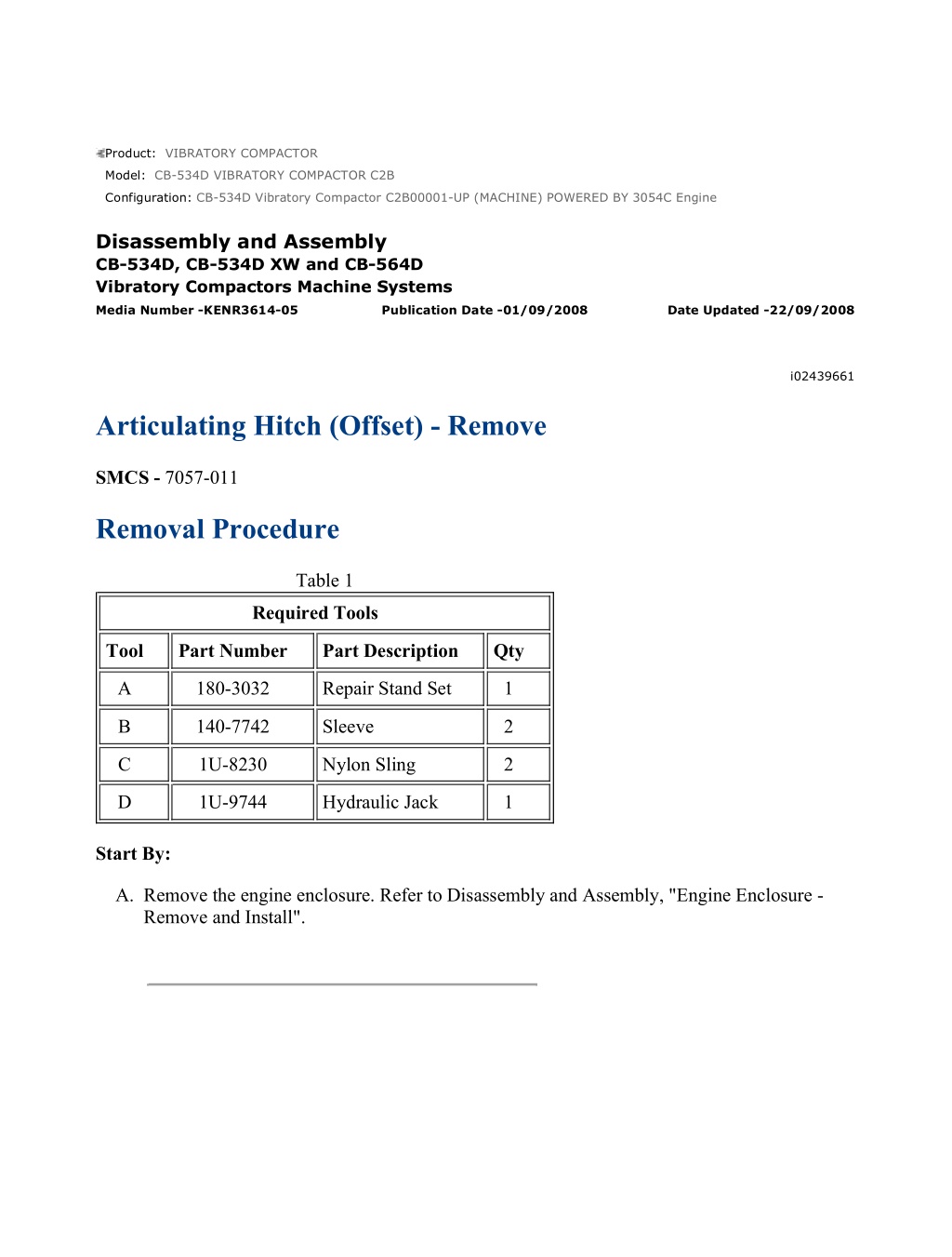
CB-534D Vibratory Compactor C2B00001-UP (MACHINE) POWERED BY 3054C ... 1/5 Product: VIBRATORY COMPACTOR Model: CB-534D VIBRATORY COMPACTOR C2B Configuration: CB-534D Vibratory Compactor C2B00001-UP (MACHINE) POWERED BY 3054C Engine Disassembly and Assembly CB-534D, CB-534D XW and CB-564D Vibratory Compactors Machine Systems Media Number -KENR3614-05 Publication Date -01/09/2008 Date Updated -22/09/2008 i02439661 Articulating Hitch (Offset) - Remove SMCS - 7057-011 Removal Procedure Table 1 Required Tools Tool Part Number Part Description Qty A 180-3032 Repair Stand Set 1 B 140-7742 Sleeve 2 C 1U-8230 Nylon Sling 2 D 1U-9744 Hydraulic Jack 1 Start By: A. Remove the engine enclosure. Refer to Disassembly and Assembly, "Engine Enclosure - Remove and Install". https://127.0.0.1/sisweb/sisweb/techdoc/techdoc_print_page.jsp?returnurl=/sisw... 2021/5/5
CB-534D Vibratory Compactor C2B00001-UP (MACHINE) POWERED BY 3054C ... 2/5 Illustration 1 g01095895 1. Raise the front of the machine and install Tooling (A) . Illustration 2 g01218305 2. Remove bolt (1) and pin assembly (2). Remove steering cylinder (4) from articulating hitch (3) . https://127.0.0.1/sisweb/sisweb/techdoc/techdoc_print_page.jsp?returnurl=/sisw... 2021/5/5
CB-534D Vibratory Compactor C2B00001-UP (MACHINE) POWERED BY 3054C ... 3/5 Illustration 3 g01095928 A typical example 3. Attach a suitable lifting device, Tooling (B), and Tooling (C) to the rear frame. Illustration 4 g01219039 4. Remove bolt (6) and pin assembly (7). Remove the offset cylinder from the hitch assembly. 5. Secure Tooling (D) to articulating hitch (3). Remove bolts (5) from each side of the front frame. 6. Remove bolts (8) from the rear frame. Lift the rear frame and move the rear frame far enough in order to provide clearance for articulating hitch (3). The weight of articulating hitch (3) is approximately 270 kg (595 lb). https://127.0.0.1/sisweb/sisweb/techdoc/techdoc_print_page.jsp?returnurl=/sisw... 2021/5/5
https://www.ebooklibonline.com Hello dear friend! Thank you very much for reading. Enter the link into your browser. The full manual is available for immediate download. https://www.ebooklibonline.com
CB-534D Vibratory Compactor C2B00001-UP (MACHINE) POWERED BY 3054C ... 4/5 Illustration 5 g01219076 7. Remove bolts (9), upper cap (10), and plug (11) . Illustration 6 g01219082 8. Remove shims (12) and shaft (13) . Illustration 7 g01219157 9. Remove bolts (14), lower cap (15), and plug (17) . https://127.0.0.1/sisweb/sisweb/techdoc/techdoc_print_page.jsp?returnurl=/sisw... 2021/5/5
CB-534D Vibratory Compactor C2B00001-UP (MACHINE) POWERED BY 3054C ... 5/5 Illustration 8 g01219160 10. Remove lip seal (17) and bearing cone (18) from the upper and lower caps. Illustration 9 g01219162 11. If necessary, remove bearing cup (19) from the upper and lower caps. 12. Repeat Steps 7 through 11 for the other end of articulating hitch. https://127.0.0.1/sisweb/sisweb/techdoc/techdoc_print_page.jsp?returnurl=/sisw... 2021/5/5
CB-534D Vibratory Compactor C2B00001-UP (MACHINE) POWERED BY 3054C ... 1/7 Product: VIBRATORY COMPACTOR Model: CB-534D VIBRATORY COMPACTOR C2B Configuration: CB-534D Vibratory Compactor C2B00001-UP (MACHINE) POWERED BY 3054C Engine Disassembly and Assembly CB-534D, CB-534D XW and CB-564D Vibratory Compactors Machine Systems Media Number -KENR3614-05 Publication Date -01/09/2008 Date Updated -22/09/2008 i03515061 Articulating Hitch (Offset) - Install SMCS - 7057-012 Installation Procedure Table 1 Required Tools Tool Part Number Part Description Qty A 180-3032 Repair Stand Set 1 B 140-7742 Sleeve 2 C 1U-8230 Nylon Sling 2 D 1U-9744 Hydraulic Jack 1 E 1P-0808 Multipurpose Grease 1 F 6V-4876 Lubricant 1 G 3B-8489 Grease Fitting 2 https://127.0.0.1/sisweb/sisweb/techdoc/techdoc_print_page.jsp?returnurl=/sisw... 2021/5/5
CB-534D Vibratory Compactor C2B00001-UP (MACHINE) POWERED BY 3054C ... 2/7 Illustration 1 g01219162 1. Install bearing cup (19) in the upper and lower caps. Illustration 2 g01219160 2. Install bearing cone (18) and lip seal (17) in the upper and lower caps. Illustration 3 g01099053 https://127.0.0.1/sisweb/sisweb/techdoc/techdoc_print_page.jsp?returnurl=/sisw... 2021/5/5
CB-534D Vibratory Compactor C2B00001-UP (MACHINE) POWERED BY 3054C ... 3/7 3. Use a digital caliper to measure the distance between the ears on the pin end of the hitch. Measure the right and left side of the counterbores. Take the average of the two measurements in order to get Dimension (X) . Subtract Dimension (X) from 250 mm (9.8 inch). This will be the required shim thickness. This shim thickness will achieve the required preload. Install shims. Illustration 4 g01219157 4. Install lower cap (15) , plug (16) , and bolts (14) . Illustration 5 g01219193 5. Apply Tooling (F) to shaft (13) , as shown. https://127.0.0.1/sisweb/sisweb/techdoc/techdoc_print_page.jsp?returnurl=/sisw... 2021/5/5
CB-534D Vibratory Compactor C2B00001-UP (MACHINE) POWERED BY 3054C ... 4/7 Illustration 6 g01219082 6. Install shaft (13) and position shims (12) . Illustration 7 g01219076 7. Install upper cap (10) , plug (11) , and bolts (9) . Tighten bolts (9) to a torque of 102 N m (75 lb ft). Illustration 8 g01218878 https://127.0.0.1/sisweb/sisweb/techdoc/techdoc_print_page.jsp?returnurl=/sisw... 2021/5/5
CB-534D Vibratory Compactor C2B00001-UP (MACHINE) POWERED BY 3054C ... 5/7 8. Remove plugs (11) and (16) from the upper and lower caps. Install Tooling (G) . Fill the caps with Tooling (F) . Remove Tooling (G) and install plugs (11) and (16) . 9. Repeat Steps 1 through 8 for the other end of the hitch assembly. Illustration 9 g01095928 A typical example 10. Attach a suitable lifting device, Tooling (B) , and Tooling (C) to the rear frame. Illustration 10 g01219039 11. Secure Tooling (D) to articulating hitch (3) . Install articulating hitch (3) in the machine. The weight of articulating hitch (3) is approximately 270 kg (595 lb). https://127.0.0.1/sisweb/sisweb/techdoc/techdoc_print_page.jsp?returnurl=/sisw... 2021/5/5
CB-534D Vibratory Compactor C2B00001-UP (MACHINE) POWERED BY 3054C ... 6/7 12. Install bolts (6) in each side of the rear frame. Install articulating hitch (3) in the machine. Tighten all bolts (6) evenly in order to keep an even gap on the right and left side of articulating hitch (3) . A gap will exist on each side of articulating hitch (3) . 13. Install bolts (5) in the front frame. Repeat Step 12. 14. Remove the suitable lifting device. Tooling (B) , Tooling (C) , and Tooling (D) from the rear frame. Illustration 11 g01218305 15. Install steering cylinder (4) to articulating hitch assembly (3) . Install pin assembly (2) and bolt (1) . Illustration 12 g01095895 16. Raise the front of the machine and install Tooling (A) . End By: Install the engine enclosure. Refer to Disassembly and Assembly, "Engine Enclosure - Remove and Install". https://127.0.0.1/sisweb/sisweb/techdoc/techdoc_print_page.jsp?returnurl=/sisw... 2021/5/5
CB-534D Vibratory Compactor C2B00001-UP (MACHINE) POWERED BY 3054C ... 1/4 Product: VIBRATORY COMPACTOR Model: CB-534D VIBRATORY COMPACTOR C2B Configuration: CB-534D Vibratory Compactor C2B00001-UP (MACHINE) POWERED BY 3054C Engine Disassembly and Assembly CB-534D, CB-534D XW and CB-564D Vibratory Compactors Machine Systems Media Number -KENR3614-05 Publication Date -01/09/2008 Date Updated -22/09/2008 i02370386 Offset Valve - Remove and Install SMCS - 5051-010 Removal Procedure Note: Put identification marks on all hoses, on all hose assemblies, on all wires, and on all tube assemblies for installation purposes. Plug all hose assemblies and all tube assemblies. This helps to prevent fluid loss, and this helps to keep contaminants from entering the system. NOTICE Care must be taken to ensure that fluids are contained during performance of inspection, maintenance, testing, adjusting and repair of the product. Be prepared to collect the fluid with suitable containers before opening any compartment or disassembling any component containing fluids. Refer to Special Publication, NENG2500, "Caterpillar Tools and Shop Products Guide" for tools and supplies suitable to collect and contain fluids on Caterpillar products. Dispose of all fluids according to local regulations and mandates. Personal injury can result from hydraulic oil pressure and hot oil. Hydraulic oil pressure can remain in the hydraulic system after the engine has been stopped. Serious injury can be caused if this pressure is not released before any service is done on the hydraulic system. https://127.0.0.1/sisweb/sisweb/techdoc/techdoc_print_page.jsp?returnurl=/sisw... 2021/5/5
CB-534D Vibratory Compactor C2B00001-UP (MACHINE) POWERED BY 3054C ... 2/4 Make sure all of the work tools have been lowered to the ground, and the oil is cool before removing any components or lines. Remove the oil filler cap only when the engine is stopped, and the filler cap is cool enough to touch with your bare hand. 1. Open the engine enclosure. Illustration 1 g01182745 2. Remove screws (3) and harness assemblies (2) from offset valve (1) . 3. Disconnect hose assemblies (5) from offset valve (1) . 4. Remove bolts (4) and offset valve (1) from the machine. Disassembly and Assembly Information Table 1 Required Tools Tool Part Number Part Description Qty A 1P-0808 Multipurpose Grease 1 B 195-4609 Seal Pick 1 https://127.0.0.1/sisweb/sisweb/techdoc/techdoc_print_page.jsp?returnurl=/sisw... 2021/5/5
CB-534D Vibratory Compactor C2B00001-UP (MACHINE) POWERED BY 3054C ... 3/4 Illustration 2 g01191826 (1) Lubricate sealing lips with a thin covering of the lubricant that is being sealed. Note: Apply Tooling (A) to the threads. Installation Procedure https://127.0.0.1/sisweb/sisweb/techdoc/techdoc_print_page.jsp?returnurl=/sisw... 2021/5/5
CB-534D Vibratory Compactor C2B00001-UP (MACHINE) POWERED BY 3054C ... 4/4 Illustration 3 g01182745 1. Install offset valve (1) and bolts (4) on the machine. 2. Connect hose assemblies (5) on offset valve (1) . 3. Install harness assemblies (2) and screws (3) on offset valve (1) . 4. Close the engine enclosure. https://127.0.0.1/sisweb/sisweb/techdoc/techdoc_print_page.jsp?returnurl=/sisw... 2021/5/5
CB-534D Vibratory Compactor C2B00001-UP (MACHINE) POWERED BY 3054C ... 1/4 Product: VIBRATORY COMPACTOR Model: CB-534D VIBRATORY COMPACTOR C2B Configuration: CB-534D Vibratory Compactor C2B00001-UP (MACHINE) POWERED BY 3054C Engine Disassembly and Assembly CB-534D, CB-534D XW and CB-564D Vibratory Compactors Machine Systems Media Number -KENR3614-05 Publication Date -01/09/2008 Date Updated -22/09/2008 i02422893 Hydraulic Cylinder (Offset) - Remove and Install SMCS - 7562-010 Removal Procedure Note: Put identification marks on all hoses, on all hose assemblies, on all wires, and on all tube assemblies for installation purposes. Plug all hose assemblies and all tube assemblies. This helps to prevent fluid loss, and this helps to keep contaminants from entering the system. NOTICE Care must be taken to ensure that fluids are contained during performance of inspection, maintenance, testing, adjusting and repair of the product. Be prepared to collect the fluid with suitable containers before opening any compartment or disassembling any component containing fluids. Refer to Special Publication, NENG2500, "Caterpillar Tools and Shop Products Guide" for tools and supplies suitable to collect and contain fluids on Caterpillar products. Dispose of all fluids according to local regulations and mandates. Personal injury can result from hydraulic oil pressure and hot oil. https://127.0.0.1/sisweb/sisweb/techdoc/techdoc_print_page.jsp?returnurl=/sisw... 2021/5/5
CB-534D Vibratory Compactor C2B00001-UP (MACHINE) POWERED BY 3054C ... 2/4 Hydraulic oil pressure can remain in the hydraulic system after the engine has been stopped. Serious injury can be caused if this pressure is not released before any service is done on the hydraulic system. Make sure all of the work tools have been lowered to the ground, and the oil is cool before removing any components or lines. Remove the oil filler cap only when the engine is stopped, and the filler cap is cool enough to touch with your bare hand. Cylinders equipped with lock valves can remain pressurized for very long periods of time, even with the hoses removed. Failure to relieve pressure before removing a lock valve or disassembling a cylinder can result in personal injury or death. Ensure all pressure is relieved before removing a lock valve or disassembling a cylinder. Illustration 1 g01210737 1. Disconnect harness assembly (1) . 2. Remove hose clamp (2) . https://127.0.0.1/sisweb/sisweb/techdoc/techdoc_print_page.jsp?returnurl=/sisw... 2021/5/5
CB-534D Vibratory Compactor C2B00001-UP (MACHINE) POWERED BY 3054C ... 3/4 Illustration 2 g01210748 3. Disconnect hose assemblies (7) . 4. Remove bolt (5) and pin assembly (6) . 5. Remove bolt (4) and pin assembly (3) . 6. Remove hydraulic cylinder (8) from the machine. Installation Procedure Illustration 3 g01210748 1. Install hydraulic cylinder (8) in the machine. 2. Install pin assembly (3) and bolt (4) . 3. Install pin assembly (6) and bolt (5) . 4. Connect hose assemblies (7) . https://127.0.0.1/sisweb/sisweb/techdoc/techdoc_print_page.jsp?returnurl=/sisw... 2021/5/5
CB-534D Vibratory Compactor C2B00001-UP (MACHINE) POWERED BY 3054C ... 4/4 Illustration 4 g01210737 5. Install hose clamp (2) . 6. Connect harness assembly (1) . https://127.0.0.1/sisweb/sisweb/techdoc/techdoc_print_page.jsp?returnurl=/sisw... 2021/5/5
CB-534D Vibratory Compactor C2B00001-UP (MACHINE) POWERED BY 3054C ... 1/3 Product: VIBRATORY COMPACTOR Model: CB-534D VIBRATORY COMPACTOR C2B Configuration: CB-534D Vibratory Compactor C2B00001-UP (MACHINE) POWERED BY 3054C Engine Disassembly and Assembly CB-534D, CB-534D XW and CB-564D Vibratory Compactors Machine Systems Media Number -KENR3614-05 Publication Date -01/09/2008 Date Updated -22/09/2008 i02373901 Vibratory Valve - Remove SMCS - 5653-011 Removal Procedure Note: Put identification marks on all hoses, on all hose assemblies, on all wires, and on all tube assemblies for installation purposes. Plug all hose assemblies and all tube assemblies. This helps to prevent fluid loss, and this helps to keep contaminants from entering the system. NOTICE Care must be taken to ensure that fluids are contained during performance of inspection, maintenance, testing, adjusting and repair of the product. Be prepared to collect the fluid with suitable containers before opening any compartment or disassembling any component containing fluids. Refer to Special Publication, NENG2500, "Caterpillar Tools and Shop Products Guide" for tools and supplies suitable to collect and contain fluids on Caterpillar products. Dispose of all fluids according to local regulations and mandates. Personal injury can result from hydraulic oil pressure and hot oil. https://127.0.0.1/sisweb/sisweb/techdoc/techdoc_print_page.jsp?returnurl=/sisw... 2021/5/5
CB-534D Vibratory Compactor C2B00001-UP (MACHINE) POWERED BY 3054C ... 2/3 Hydraulic oil pressure can remain in the hydraulic system after the engine has been stopped. Serious injury can be caused if this pressure is not released before any service is done on the hydraulic system. Make sure all of the work tools have been lowered to the ground, and the oil is cool before removing any components or lines. Remove the oil filler cap only when the engine is stopped, and the filler cap is cool enough to touch with your bare hand. Illustration 1 g01184397 1. Disconnect hose assemblies (1) from vibratory valve (2) . Illustration 2 g01184405 2. Disconnect hose assemblies (3) from the back side of vibratory valve (2) . https://127.0.0.1/sisweb/sisweb/techdoc/techdoc_print_page.jsp?returnurl=/sisw... 2021/5/5
CB-534D Vibratory Compactor C2B00001-UP (MACHINE) POWERED BY 3054C ... 3/3 Illustration 3 g01184466 3. Disconnect harness assemblies (4) from vibratory valve (2) . Illustration 4 g01184426 4. Disconnect hose assemblies (5) from both sides of vibratory valve (2) . 5. Remove bolts (6) and clips (7) . 6. Disconnect harness assemblies (9) . 7. Remove bolts (8) and vibratory valve (2) from the machine. https://127.0.0.1/sisweb/sisweb/techdoc/techdoc_print_page.jsp?returnurl=/sisw... 2021/5/5
CB-534D Vibratory Compactor C2B00001-UP (MACHINE) POWERED BY 3054C ... 1/3 Product: VIBRATORY COMPACTOR Model: CB-534D VIBRATORY COMPACTOR C2B Configuration: CB-534D Vibratory Compactor C2B00001-UP (MACHINE) POWERED BY 3054C Engine Disassembly and Assembly CB-534D, CB-534D XW and CB-564D Vibratory Compactors Machine Systems Media Number -KENR3614-05 Publication Date -01/09/2008 Date Updated -22/09/2008 i02377461 Vibratory Valve - Disassemble SMCS - 5653-015 Disassembly Procedure Note: This component is being disassembled and displayed for CLEANING PURPOSES ONLY. Many internal parts are not available for this component. Care must be taken during disassembly and assembly in order to prevent damage to unavailable parts. NOTICE Keep all parts clean from contaminants. Contamination of the hydraulic system with foreign material will reduce the service life of the hydraulic system components. To prevent contaminants from entering the hydraulic system, always plug or cap the lines, fittings, or hoses as they are disconnected. Cover any disassembled components and clean them properly before assembly. Clean the hydraulic system properly after any major component exchange or especially after a component failure, to remove any contamination. https://127.0.0.1/sisweb/sisweb/techdoc/techdoc_print_page.jsp?returnurl=/sisw... 2021/5/5
CB-534D Vibratory Compactor C2B00001-UP (MACHINE) POWERED BY 3054C ... 2/3 Illustration 1 g01186426 Personal injury can result from being struck by parts propelled by a released spring force. Make sure to wear all necessary protective equipment. Follow the recommended procedure and use all recommended tooling to release the spring force. 1. Remove bolts (1) and flushing valve (2) from valve body (5) . 2. Remove O-ring seals (3) from flushing valve (2) . 3. Remove relief valve (4) from valve body (5) . 4. Remove coil (9) from cartridge (7) . 5. Remove seals (8) from coil (9) . 6. Remove cartridge (7) from valve body (5) . 7. Remove seals (6) from cartridge (7) . 8. Remove coil (13) from cartridge (11) . https://127.0.0.1/sisweb/sisweb/techdoc/techdoc_print_page.jsp?returnurl=/sisw... 2021/5/5
CB-534D Vibratory Compactor C2B00001-UP (MACHINE) POWERED BY 3054C ... 3/3 9. Remove seals (12) from coil (13) . 10. Remove cartridge (11) from valve body (5) . 11. Remove seals (10) from cartridge (11) . 12. Remove plug (17) from valve body (5) . 13. Remove O-ring seal (16) from plug (17) . 14. Remove plug (15) from valve body (5) . 15. Remove O-ring seal (14) from plug (15) . https://127.0.0.1/sisweb/sisweb/techdoc/techdoc_print_page.jsp?returnurl=/sisw... 2021/5/5
CB-534D Vibratory Compactor C2B00001-UP (MACHINE) POWERED BY 3054C ... 1/3 Product: VIBRATORY COMPACTOR Model: CB-534D VIBRATORY COMPACTOR C2B Configuration: CB-534D Vibratory Compactor C2B00001-UP (MACHINE) POWERED BY 3054C Engine Disassembly and Assembly CB-534D, CB-534D XW and CB-564D Vibratory Compactors Machine Systems Media Number -KENR3614-05 Publication Date -01/09/2008 Date Updated -22/09/2008 i02377637 Vibratory Valve - Assemble SMCS - 5653-016 Assembly Procedure Note: Cleanliness is an important factor. Before assembly, thoroughly clean all parts in cleaning fluid. Allow the parts to air dry. Do not use wiping cloths or rags to dry parts. Lint may be deposited on the parts which may cause trouble. Inspect all parts. If any parts are worn or damaged, use new parts for replacement. Dirt and other contaminants can damage the precision component. Perform assembly procedures on a clean work surface. Keep components covered and protected at all times. Note: Check the O-ring seals, the gaskets, and the seals for wear or for damage. Replace the components, if necessary. https://127.0.0.1/sisweb/sisweb/techdoc/techdoc_print_page.jsp?returnurl=/sisw... 2021/5/5
Suggest: If the above button click is invalid. Please download this document first, and then click the above link to download the complete manual. Thank you so much for reading
CB-534D Vibratory Compactor C2B00001-UP (MACHINE) POWERED BY 3054C ... 2/3 Illustration 1 g01186426 1. Install O-ring seal (14) on plug (15) . 2. Install plug (15) in valve body (5) . 3. Install O-ring seal (16) on plug (17) . 4. Install plug (17) in valve body (5) . 5. Install seals (10) on cartridge (11) . 6. Install cartridge (11) in valve body (5) . 7. Install seals (12) on coil (13) . 8. Install coil (13) in cartridge (11) . 9. Install seals (6) on cartridge (7) . 10. Install cartridge (7) in valve body (5) . 11. Install seals (8) on coil (9) . 12. Install coil (9) in cartridge (7) . 13. Install relief valve (4) in valve body (5) . 14. Install O-ring seals (3) in flushing valve (2) . 15. Install flushing valve (2) and bolts (1) on valve body (5) . https://127.0.0.1/sisweb/sisweb/techdoc/techdoc_print_page.jsp?returnurl=/sisw... 2021/5/5
https://www.ebooklibonline.com Hello dear friend! Thank you very much for reading. Enter the link into your browser. The full manual is available for immediate download. https://www.ebooklibonline.com

