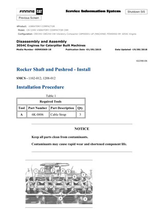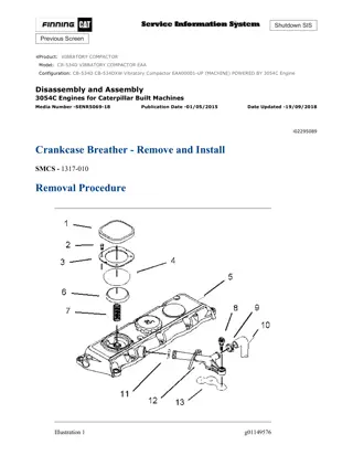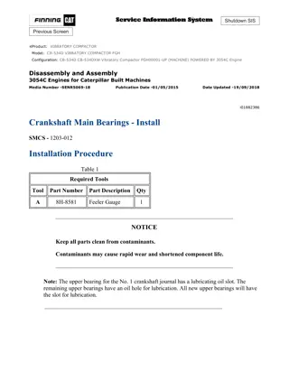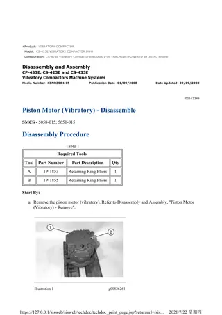
Caterpillar Cat CB-534C VIBRATORY COMPACTOR (Prefix 5HN) Service Repair Manual Instant Download
Please open the website below to get the complete manualnn//
Download Presentation

Please find below an Image/Link to download the presentation.
The content on the website is provided AS IS for your information and personal use only. It may not be sold, licensed, or shared on other websites without obtaining consent from the author. Download presentation by click this link. If you encounter any issues during the download, it is possible that the publisher has removed the file from their server.
E N D
Presentation Transcript
CB-534C Vibratory Compactor 5HN00001-UP (MACHINE) POWERED BY 3054 En... 1/3 Shutdown SIS Previous Screen Product: VIBRATORY COMPACTOR Model: CB-534C VIBRATORY COMPACTOR 5HN Configuration: CB-534C Vibratory Compactor 5HN00001-UP (MACHINE) POWERED BY 3054 Engine Disassembly and Assembly 3054 Engine for Caterpillar Built Machines Media Number -SENR6241-13 Publication Date -01/08/2008 Date Updated -04/08/2008 i04406238 Flywheel - Remove SMCS - 1156-011 Removal Procedure Table 1 Required Tools Tool Part Number Part Description Qty A 138-7575 Link Bracket 1 NOTICE Keep all parts clean from contaminants. Contaminants may cause rapid wear and shortened component life. https://127.0.0.1/sisweb/sisweb/techdoc/techdoc_print_page.jsp?returnurl=/sisw... 2021/5/8
CB-534C Vibratory Compactor 5HN00001-UP (MACHINE) POWERED BY 3054 En... 2/3 Illustration 1 g00546794 Typical Example. Different lifting device shown than what is called out in the Table. Illustration 2 g00546793 1. Install Tool (A) and a suitable lifting device on flywheel (1) . 2. Remove bolts (3) and bearing housing (4) . 3. Remove six bolts (2) and the washers from the flywheel. Note: The 3054 and 3056 marine engines used several bolt patterns to attach the flywheel to the crankshaft. There are drilled holes that are not used in the crankshaft and in the flywheel. 4. Use the suitable lifting device in order to remove flywheel (1) . The weight of flywheel (1) and the flywheel ring gear is 53 kg (120 lb). 5. If removal of the flywheel ring gear is necessary, place an index mark on the chamfer of the flywheel ring gear for the installation process. Illustration 3 g00546795 https://127.0.0.1/sisweb/sisweb/techdoc/techdoc_print_page.jsp?returnurl=/sisw... 2021/5/8
CB-534C Vibratory Compactor 5HN00001-UP (MACHINE) POWERED BY 3054 En... 3/3 6. Use a hammer and a punch in order to remove flywheel ring gear (5) from flywheel (1) . Copyright 1993 - 2021 Caterpillar Inc. Sat May 8 23:12:05 UTC+0800 2021 All Rights Reserved. Private Network For SIS Licensees. https://127.0.0.1/sisweb/sisweb/techdoc/techdoc_print_page.jsp?returnurl=/sisw... 2021/5/8
https://www.ebooklibonline.com Hello dear friend! Thank you very much for reading. Enter the link into your browser. The full manual is available for immediate download. https://www.ebooklibonline.com
CB-534C Vibratory Compactor 5HN00001-UP (MACHINE) POWERED BY 3054 En... 1/2 Shutdown SIS Previous Screen Product: VIBRATORY COMPACTOR Model: CB-534C VIBRATORY COMPACTOR 5HN Configuration: CB-534C Vibratory Compactor 5HN00001-UP (MACHINE) POWERED BY 3054 Engine Disassembly and Assembly 3054 Engine for Caterpillar Built Machines Media Number -SENR6241-13 Publication Date -01/08/2008 Date Updated -04/08/2008 i04406239 Flywheel - Install SMCS - 1156-012 Installation Procedure Table 1 Required Tools Tool Part Number Part Description Qty A 138-7575 Link Bracket 1 Always wear protective gloves when handling parts that have been heated. https://127.0.0.1/sisweb/sisweb/techdoc/techdoc_print_page.jsp?returnurl=/sisw... 2021/5/8
CB-534C Vibratory Compactor 5HN00001-UP (MACHINE) POWERED BY 3054 En... 2/2 Illustration 1 g00803517 Typical Example. Different Lifting device shown than what is called out in the table. 1. If flywheel ring gear (5) was removed, heat flywheel ring gear (5) to a temperature of 250 C (480 F). Note: Do not use a torch to heat the flywheel ring gear. 2. Install flywheel ring gear (5) on flywheel (1) . Note: Ensure that the chamfer of the flywheel ring gear is in the correct position on the flywheel. 3. Install Tool (A) and a suitable lifting device on flywheel (1) and position flywheel (1) in the flywheel housing. The weight of flywheel (1) and flywheel ring gear (5) is 53 kg (120 lb). Illustration 2 g00546793 4. Install six bolts (2) and the washers that hold flywheel (1) in position. Tighten the bolts to a torque of 105 N m (77 lb ft). 5. Put bearing housing (4) in position on the flywheel. Install four bolts (3) that fasten bearing housing (4) to the flywheel. 6. Refer to the Specifications Module, "Flywheel" topic for information on inspecting the flywheel. Copyright 1993 - 2021 Caterpillar Inc. Sat May 8 23:13:01 UTC+0800 2021 All Rights Reserved. Private Network For SIS Licensees. https://127.0.0.1/sisweb/sisweb/techdoc/techdoc_print_page.jsp?returnurl=/sisw... 2021/5/8
CB-534C Vibratory Compactor 5HN00001-UP (MACHINE) POWERED BY 3054 En... 1/3 Shutdown SIS Previous Screen Product: VIBRATORY COMPACTOR Model: CB-534C VIBRATORY COMPACTOR 5HN Configuration: CB-534C Vibratory Compactor 5HN00001-UP (MACHINE) POWERED BY 3054 Engine Disassembly and Assembly 3054 Engine for Caterpillar Built Machines Media Number -SENR6241-13 Publication Date -01/08/2008 Date Updated -04/08/2008 i01741403 Crankshaft Rear Seal - Remove SMCS - 1161-011 Removal Procedure Start By: a. Remove the flywheel. Refer to Disassembly and Assembly, "Flywheel - Remove". NOTICE Keep all parts clean from contaminants. Contaminants may cause rapid wear and shortened component life. NOTICE Care must be taken to ensure that fluids are contained during performance of inspection, maintenance, testing, adjusting and repair of the product. Be prepared to collect the fluid with suitable containers before opening any compartment or disassembling any component containing fluids. Refer to Special Publication, NENG2500, "Caterpillar Dealer Service Tool Catalog" for tools and supplies suitable to collect and contain fluids on Caterpillar products. Dispose of all fluids according to local regulations and mandates. https://127.0.0.1/sisweb/sisweb/techdoc/techdoc_print_page.jsp?returnurl=/sisw... 2021/5/8
CB-534C Vibratory Compactor 5HN00001-UP (MACHINE) POWERED BY 3054 En... 2/3 Engines with 14 Bolt Housing Assembly Illustration 1 g00632744 The flywheel housing has been removed for photographic purposes only. 1. Remove bolts (1) from housing (3). 2. Remove socket head bolts (2) from housing (3). 3. Remove the crankshaft rear seal, the gasket, and housing (3) from the dowels in the cylinder block. Engines with 10 Bolt Housing Assembly Note: The 10 bolt housing assembly is manufactured as a one-piece assembly. The 10 bolt housing assembly is NOT adaptable to engines that have the 14 bolt housing assembly. Illustration 2 g00830867 https://127.0.0.1/sisweb/sisweb/techdoc/techdoc_print_page.jsp?returnurl=/sisw... 2021/5/8
CB-534C Vibratory Compactor 5HN00001-UP (MACHINE) POWERED BY 3054 En... 3/3 1. Remove the bolts in reverse order of the numbered sequence. Refer to Illustration 2. 2. Remove the one-piece housing assembly from the cylinder block. Copyright 1993 - 2021 Caterpillar Inc. Sat May 8 23:13:57 UTC+0800 2021 All Rights Reserved. Private Network For SIS Licensees. https://127.0.0.1/sisweb/sisweb/techdoc/techdoc_print_page.jsp?returnurl=/sisw... 2021/5/8
CB-534C Vibratory Compactor 5HN00001-UP (MACHINE) POWERED BY 3054 En... 1/4 Shutdown SIS Previous Screen Product: VIBRATORY COMPACTOR Model: CB-534C VIBRATORY COMPACTOR 5HN Configuration: CB-534C Vibratory Compactor 5HN00001-UP (MACHINE) POWERED BY 3054 Engine Disassembly and Assembly 3054 Engine for Caterpillar Built Machines Media Number -SENR6241-13 Publication Date -01/08/2008 Date Updated -04/08/2008 i01605362 Crankshaft Rear Seal - Install SMCS - 1161-012 Installation Procedure Table 1 Required Tools Tool Part Number Part Description Qty 9U-6205 Rear Seal Installer 1 A 1P-0510 Driver Group 1 B FT-2806 Alignment Tool 1 NOTICE Keep all parts clean from contaminants. Contaminants may cause rapid wear and shortened component life. Engines with 14 Bolt Housing Assembly 1. Inspect the condition of the gasket. Replace the gasket, if necessary. 2. Clean the areas of the parts that will contact each other. https://127.0.0.1/sisweb/sisweb/techdoc/techdoc_print_page.jsp?returnurl=/sisw... 2021/5/8
CB-534C Vibratory Compactor 5HN00001-UP (MACHINE) POWERED BY 3054 En... 2/4 Illustration 1 g00541839 3. Use Tool (A) and a suitable press to install the crankshaft rear seal into the housing. Make sure that you install the seal to the correct depth in the housing. Refer to Specifications, "Crankshaft Seals" for additional information. 4. Lubricate the crankshaft flange and the lip of the crankshaft rear seal with clean engine oil. 5. Install Tool (A) onto the crankshaft flange. 6. Put the new gasket for the housing in position on the dowels in the cylinder block. Illustration 2 g00606404 7. Carefully place housing (3) and crankshaft rear seal (4) over Tool (A) . 8. Position housing (3) on the dowels in the cylinder block. 9. Remove Tool (A) . https://127.0.0.1/sisweb/sisweb/techdoc/techdoc_print_page.jsp?returnurl=/sisw... 2021/5/8
CB-534C Vibratory Compactor 5HN00001-UP (MACHINE) POWERED BY 3054 En... 3/4 Illustration 3 g00606340 The flywheel housing has been removed for photographic purposes only. 10. Install bolts (1) and socket head bolts (2) that fasten housing (3) to the cylinder block. 11. Tighten all of the bolts to a torque of 22 N m (16 lb ft). Engines with 10 Bolt Housing Assembly Note: The 10 bolt housing assembly is manufactured as a one-piece assembly. The 10 bolt housing assembly is NOT adaptable to engines that have the 14 bolt housing assembly. 1. Ensure that all parts and surfaces of the engine block are clean and free from oil, grease, and dirt. Illustration 4 g00831176 https://127.0.0.1/sisweb/sisweb/techdoc/techdoc_print_page.jsp?returnurl=/sisw... 2021/5/8
CB-534C Vibratory Compactor 5HN00001-UP (MACHINE) POWERED BY 3054 En... 4/4 Note: The crankshaft rear seal is lubricated. There is no need to lubricate the seal or the crankshaft flange before installation. 2. Place housing assembly (3) on crankshaft flange (1) until the housing assembly contacts the cylinder block face. Plastic sleeve (2) will push out of the housing assembly. Discard the plastic sleeve after the housing assembly is installed. 3. Place Tool (B) over housing assembly (3). This will center the housing assembly onto the crankshaft flange. Illustration 5 g00830867 4. Install the bolts with Tool (B) in position in order to fasten housing assembly (3) to the cylinder block. Tighten bolts 1 and 2 to a torque of 22 N m (16 lb ft). 5. Remove Tool (B). Tighten the remaining bolts in sequence to a torque of 22 N m (16 lb ft). End By: Install the flywheel. Refer to Disassembly and Assembly, "Flywheel - Install". Copyright 1993 - 2021 Caterpillar Inc. Sat May 8 23:14:53 UTC+0800 2021 All Rights Reserved. Private Network For SIS Licensees. https://127.0.0.1/sisweb/sisweb/techdoc/techdoc_print_page.jsp?returnurl=/sisw... 2021/5/8
CB-534C Vibratory Compactor 5HN00001-UP (MACHINE) POWERED BY 3054 En... 1/4 Shutdown SIS Previous Screen Product: VIBRATORY COMPACTOR Model: CB-534C VIBRATORY COMPACTOR 5HN Configuration: CB-534C Vibratory Compactor 5HN00001-UP (MACHINE) POWERED BY 3054 Engine Disassembly and Assembly 3054 Engine for Caterpillar Built Machines Media Number -SENR6241-13 Publication Date -01/08/2008 Date Updated -04/08/2008 i01741450 Flywheel Housing - Remove and Install SMCS - 1157-010 Removal Procedure Table 1 Required Tools Tool Part Number Part Description Qty A 138-7574 Link Bracket 2 Start By: a. Remove the electric starting motor. Refer to Disassembly and Assembly, "Electric Starting Motor - Remove and Install". b. Remove the flywheel. Refer to Disassembly and Assembly, "Flywheel - Remove". NOTICE Keep all parts clean from contaminants. Contaminants may cause rapid wear and shortened component life. NOTICE Care must be taken to ensure that fluids are contained during performance of inspection, maintenance, testing, adjusting and repair of the product. Be prepared to collect the fluid with suitable containers https://127.0.0.1/sisweb/sisweb/techdoc/techdoc_print_page.jsp?returnurl=/sisw... 2021/5/8
CB-534C Vibratory Compactor 5HN00001-UP (MACHINE) POWERED BY 3054 En... 2/4 before opening any compartment or disassembling any component containing fluids. Refer to Special Publication, NENG2500, "Caterpillar Dealer Service Tool Catalog" for tools and supplies suitable to collect and contain fluids on Caterpillar products. Dispose of all fluids according to local regulations and mandates. 1. Support the engine with blocks or with a suitable lifting device on a flat level surface. Illustration 1 g00541891 Typical example 2. Remove mounting bolts (1) from the top of flywheel housing (2). Illustration 2 g00541892 Typical example 3. Attach Tooling (A) and a suitable lifting device to flywheel housing (2). 4. Remove mounting bolts (3) that attach the flywheel housing to the cylinder block. https://127.0.0.1/sisweb/sisweb/techdoc/techdoc_print_page.jsp?returnurl=/sisw... 2021/5/8
CB-534C Vibratory Compactor 5HN00001-UP (MACHINE) POWERED BY 3054 En... 3/4 5. Remove flywheel housing (2). If necessary, hit flywheel housing (2) with a soft faced hammer in order to separate flywheel housing (2) from the cylinder block. The weight of flywheel housing (2) is approximately 32 kg (70 lb). Installation Procedure Table 2 Required Tools Tool Part Number Part Description Qty A 138-7574 Link Bracket 2 NOTICE Keep all parts clean from contaminants. Contaminants may cause rapid wear and shortened component life. 1. Clean the rear face of the cylinder block and the mating surface of the flywheel housing. Inspect the felt seal on the rear flange of the engine oil pan. Replace the felt seal, if necessary. Inspect the dowels in the cylinder block that align the flywheel housing. Replace the dowels, if necessary. Illustration 3 g00541892 2. Use Tooling (A) and a suitable lifting device to position flywheel housing (2) on the dowels that are on the cylinder block. The weight of flywheel housing (2) is approximately 32 kg (70 lb). 3. Install mounting bolts (3). https://127.0.0.1/sisweb/sisweb/techdoc/techdoc_print_page.jsp?returnurl=/sisw... 2021/5/8
CB-534C Vibratory Compactor 5HN00001-UP (MACHINE) POWERED BY 3054 En... 4/4 Illustration 4 g00541891 Typical example 4. Install mounting bolts (1) that attach flywheel housing (2) to the cylinder block. Tighten the bolts for an aluminum flywheel housing to a torque of 70 N m (52 lb ft). Tighten the cast iron flywheel housing bolts to the following torque: M10 "8.8" ... 44 N m (33 lb ft) M10 "10.9" ... 63 N m (46 lb ft) M12 "8.8" ... 75 N m (55 lb ft) M12 "10.9" ... 115 N m (85 lb ft) 5. Remove Tooling (A) from the flywheel housing. End By: a. Install the flywheel. Refer to Disassembly and Assembly, "Flywheel - Install". b. Install the electric starting motor. Refer to Disassembly and Assembly, "Electric Starting Motor - Remove and Install". Copyright 1993 - 2021 Caterpillar Inc. Sat May 8 23:15:48 UTC+0800 2021 All Rights Reserved. Private Network For SIS Licensees. https://127.0.0.1/sisweb/sisweb/techdoc/techdoc_print_page.jsp?returnurl=/sisw... 2021/5/8
CB-534C Vibratory Compactor 5HN00001-UP (MACHINE) POWERED BY 3054 En... 1/2 Shutdown SIS Previous Screen Product: VIBRATORY COMPACTOR Model: CB-534C VIBRATORY COMPACTOR 5HN Configuration: CB-534C Vibratory Compactor 5HN00001-UP (MACHINE) POWERED BY 3054 Engine Disassembly and Assembly 3054 Engine for Caterpillar Built Machines Media Number -SENR6241-13 Publication Date -01/08/2008 Date Updated -04/08/2008 i01461242 Crankshaft Pulley - Remove and Install SMCS - 1205-010 Removal Procedure Start By: A. Remove the V-Belts. Refer to Disassembly and Assembly, "V-Belts - Remove and Install". Illustration 1 g00553762 Typical example 1. Remove three bolts (2) that hold thrust block (3) in position. 2. Remove thrust block (3) from the end of the crankshaft. The thrust block holds the crankshaft pulley in position on the end of the crankshaft. 3. Remove crankshaft pulley (1) from the engine. https://127.0.0.1/sisweb/sisweb/techdoc/techdoc_print_page.jsp?returnurl=/sisw... 2021/5/8
CB-534C Vibratory Compactor 5HN00001-UP (MACHINE) POWERED BY 3054 En... 2/2 Note: Some engines have a water immersion seal that is placed on the front cover. The seal has a flexible lip on the front. The plastic mandrel that is supplied with the seal must be installed in the seal when the crankshaft pulley is removed. This will ensure that the lip maintains the correct shape. Installation Procedure Illustration 2 g00553762 Typical example 1. Remove the plastic mandrel, if necessary. 2. Put crankshaft pulley (1) in position on the crankshaft. 3. Apply 9S-3263 Thread Lock Compound to the threads of three bolts (2) . 4. Put thrust block (3) in position and align the holes with the holes in the end of the crankshaft. Note: It may be necessary to keep the crankshaft from rotating while you torque bolts (3). Use the appropriate tools in order to keep the crankshaft from rotating. 5. Install three bolts (2) that hold the thrust block in position. Tighten bolts (2) to a torque of 115 N m (85 lb ft). End By: Install the V-Belts. Refer to Disassembly and Assembly, "V-Belts - Remove and Install". Copyright 1993 - 2021 Caterpillar Inc. Sat May 8 23:16:44 UTC+0800 2021 All Rights Reserved. Private Network For SIS Licensees. https://127.0.0.1/sisweb/sisweb/techdoc/techdoc_print_page.jsp?returnurl=/sisw... 2021/5/8
CB-534C Vibratory Compactor 5HN00001-UP (MACHINE) POWERED BY 3054 En... 1/2 Shutdown SIS Previous Screen Product: VIBRATORY COMPACTOR Model: CB-534C VIBRATORY COMPACTOR 5HN Configuration: CB-534C Vibratory Compactor 5HN00001-UP (MACHINE) POWERED BY 3054 Engine Disassembly and Assembly 3054 Engine for Caterpillar Built Machines Media Number -SENR6241-13 Publication Date -01/08/2008 Date Updated -04/08/2008 i01742537 Crankshaft Front Seal - Remove SMCS - 1160-011 Removal Procedure Table 1 Required Tools Tool Part Number Part Description Qty A 1U-8145 Drill Bit 1 B 1U-7600 Slide Hammer Puller 1 Start By: a. Remove the crankshaft pulley. Refer to Disassembly and Assembly, "Crankshaft Pulley - Remove and Install". NOTICE Keep all parts clean from contaminants. Contaminants may cause rapid wear and shortened component life. NOTICE Care must be taken to ensure that fluids are contained during performance of inspection, maintenance, testing, adjusting and repair of the product. Be prepared to collect the fluid with suitable containers https://127.0.0.1/sisweb/sisweb/techdoc/techdoc_print_page.jsp?returnurl=/sisw... 2021/5/8
CB-534C Vibratory Compactor 5HN00001-UP (MACHINE) POWERED BY 3054 En... 2/2 before opening any compartment or disassembling any component containing fluids. Refer to Special Publication, NENG2500, "Caterpillar Dealer Service Tool Catalog" for tools and supplies suitable to collect and contain fluids on Caterpillar products. Dispose of all fluids according to local regulations and mandates. Illustration 1 g00541748 Typical example 1. Use Tooling (A) to drill three evenly spaced holes in crankshaft front seal (1). 2. Place Tooling (B) in the holes in order to remove crankshaft front seal (1). Use Tooling (B) in each of the three holes to evenly remove the crankshaft front seal. Note: Do not damage the flange of the crankshaft during the removal process for the crankshaft front seal. NOTICE Ensure that the main lip is used in order to remove the crankshaft front seal. Do not damage the edge of the housing for the crankshaft front seal. Copyright 1993 - 2021 Caterpillar Inc. Sat May 8 23:17:40 UTC+0800 2021 All Rights Reserved. Private Network For SIS Licensees. https://127.0.0.1/sisweb/sisweb/techdoc/techdoc_print_page.jsp?returnurl=/sisw... 2021/5/8
CB-534C Vibratory Compactor 5HN00001-UP (MACHINE) POWERED BY 3054 En... 1/3 Shutdown SIS Previous Screen Product: VIBRATORY COMPACTOR Model: CB-534C VIBRATORY COMPACTOR 5HN Configuration: CB-534C Vibratory Compactor 5HN00001-UP (MACHINE) POWERED BY 3054 Engine Disassembly and Assembly 3054 Engine for Caterpillar Built Machines Media Number -SENR6241-13 Publication Date -01/08/2008 Date Updated -04/08/2008 i01742545 Crankshaft Front Seal - Install SMCS - 1160-012 Installation Procedure Table 1 Required Tools Tool Part Number Part Description Qty A 9U-6210 Front Seal Installer 1 NOTICE Keep all parts clean from contaminants. Contaminants may cause rapid wear and shortened component life. 1. Clean the housing for the crankshaft front seal and inspect the housing for damage. 2. Lubricate the lip of the crankshaft front seal with clean engine oil. https://127.0.0.1/sisweb/sisweb/techdoc/techdoc_print_page.jsp?returnurl=/sisw... 2021/5/8
CB-534C Vibratory Compactor 5HN00001-UP (MACHINE) POWERED BY 3054 En... 2/3 Illustration 1 g00541748 3. Place crankshaft front oil seal (1) into the housing. NOTICE Ensure that the lip of the crankshaft front seal that is spring loaded is facing toward the inside of the front housing and that it is square with the bore of the housing for the crankshaft front seal. Illustration 2 g00622033 4. Use Tooling (A) to install crankshaft front oil seal (1). 5. Apply clean engine oil on the area of the crankshaft pulley that will be in contact with crankshaft front seal (1). End By: a. Install the crankshaft pulley. Refer to Disassembly and Assembly, "Crankshaft Pulley - Remove and Install". Sat May 8 23:18:35 UTC+0800 2021 https://127.0.0.1/sisweb/sisweb/techdoc/techdoc_print_page.jsp?returnurl=/sisw... 2021/5/8
CB-534C Vibratory Compactor 5HN00001-UP (MACHINE) POWERED BY 3054 En... 3/3 Copyright 1993 - 2021 Caterpillar Inc. All Rights Reserved. Private Network For SIS Licensees. https://127.0.0.1/sisweb/sisweb/techdoc/techdoc_print_page.jsp?returnurl=/sisw... 2021/5/8
CB-534C Vibratory Compactor 5HN00001-UP (MACHINE) POWERED BY 3054 En... 1/2 Shutdown SIS Previous Screen Product: VIBRATORY COMPACTOR Model: CB-534C VIBRATORY COMPACTOR 5HN Configuration: CB-534C Vibratory Compactor 5HN00001-UP (MACHINE) POWERED BY 3054 Engine Disassembly and Assembly 3054 Engine for Caterpillar Built Machines Media Number -SENR6241-13 Publication Date -01/08/2008 Date Updated -04/08/2008 i02108315 Front Cover - Remove SMCS - 1166-011 Removal Procedure Start By: A. Remove the crankshaft pulley. Refer to Disassembly and Assembly, "Crankshaft Pulley - Remove and Install". B. Remove the water pump. Refer to Disassembly and Assembly, "Water Pump - Remove". C. Remove the alternator. Refer to Disassembly and Assembly, "Alternator - Remove and Install". Illustration 1 g00640000 1. Remove bolts (1) and nuts (3) from the front cover. 2. Remove front cover (2) and the gasket from the cylinder block. Sat May 8 23:19:31 UTC+0800 2021 https://127.0.0.1/sisweb/sisweb/techdoc/techdoc_print_page.jsp?returnurl=/sisw... 2021/5/8
CB-534C Vibratory Compactor 5HN00001-UP (MACHINE) POWERED BY 3054 En... 2/2 Copyright 1993 - 2021 Caterpillar Inc. All Rights Reserved. Private Network For SIS Licensees. https://127.0.0.1/sisweb/sisweb/techdoc/techdoc_print_page.jsp?returnurl=/sisw... 2021/5/8
CB-534C Vibratory Compactor 5HN00001-UP (MACHINE) POWERED BY 3054 En... 1/3 Shutdown SIS Previous Screen Product: VIBRATORY COMPACTOR Model: CB-534C VIBRATORY COMPACTOR 5HN Configuration: CB-534C Vibratory Compactor 5HN00001-UP (MACHINE) POWERED BY 3054 Engine Disassembly and Assembly 3054 Engine for Caterpillar Built Machines Media Number -SENR6241-13 Publication Date -01/08/2008 Date Updated -04/08/2008 i01694904 Front Cover - Install SMCS - 1166-012 Installation Procedure Table 1 Required Tools Tool Part Number Part Description Qty A 9U-6210 Front Seal Installer 1 B 4C-5501 Front Cover Installer 1 NOTICE Keep all parts clean from contaminants. Contaminants may cause rapid wear and shortened component life. 1. Clean all surfaces of the front housing and clean the front cover thoroughly. 2. If necessary, use Tool (A) to install the crankshaft front oil seal. Refer to Disassembly and Assembly, "Crankshaft Front Seal - Install". https://127.0.0.1/sisweb/sisweb/techdoc/techdoc_print_page.jsp?returnurl=/sisw... 2021/5/8
CB-534C Vibratory Compactor 5HN00001-UP (MACHINE) POWERED BY 3054 En... 2/3 Illustration 1 g00640000 Illustration 2 g00546873 3. Install a new gasket and front cover (2) . 4. Install two bolts (1) in order to hold the gasket and the cover in place. 5. Use Tool (B) and the bolts for the crankshaft pulley in order to center the front cover. NOTICE The location of the front cover is critical. If the front cover is not centered, the backlash between the fuel injection pump gear and the water pump gear could be affected. This could result in damage to the fuel injection pump. 6. Install the remaining bolts (1) and the two nuts (3). Tighten the nuts and the bolts to a torque of 22 N m (16 lb ft). End By: https://127.0.0.1/sisweb/sisweb/techdoc/techdoc_print_page.jsp?returnurl=/sisw... 2021/5/8
CB-534C Vibratory Compactor 5HN00001-UP (MACHINE) POWERED BY 3054 En... 3/3 a. Install the alternator. Refer to Disassembly and Assembly, "Alternator - Remove and Install". b. Install the water pump. Refer to Disassembly and Assembly, "Water Pump - Install". c. Install the crankshaft pulley. Refer to Disassembly and Assembly, "Crankshaft Pulley - Remove and Install". Copyright 1993 - 2021 Caterpillar Inc. Sat May 8 23:20:27 UTC+0800 2021 All Rights Reserved. Private Network For SIS Licensees. https://127.0.0.1/sisweb/sisweb/techdoc/techdoc_print_page.jsp?returnurl=/sisw... 2021/5/8
CB-534C Vibratory Compactor 5HN00001-UP (MACHINE) POWERED BY 3054 En... 1/3 Shutdown SIS Previous Screen Product: VIBRATORY COMPACTOR Model: CB-534C VIBRATORY COMPACTOR 5HN Configuration: CB-534C Vibratory Compactor 5HN00001-UP (MACHINE) POWERED BY 3054 Engine Disassembly and Assembly 3054 Engine for Caterpillar Built Machines Media Number -SENR6241-13 Publication Date -01/08/2008 Date Updated -04/08/2008 i02253357 Gear Group (Front) - Remove SMCS - 1206-011 Removal Procedure Table 1 Required Tools Tool Part Number Part Description Qty A 8S-2264 Puller Group 1 B 173-9774 Wrench Bit 1 Start By: A. Remove the front cover. Refer to Disassembly and Assembly, "Front Cover - Remove". NOTICE Keep all parts clean from contaminants. Contaminants may cause rapid wear and shortened component life. https://127.0.0.1/sisweb/sisweb/techdoc/techdoc_print_page.jsp?returnurl=/sisw... 2021/5/8
CB-534C Vibratory Compactor 5HN00001-UP (MACHINE) POWERED BY 3054 En... 2/3 Illustration 1 g00556563 Note: It may be necessary to pin the fuel pump in order to maintain the correct timing. Refer to Disassembly and Assembly, "Fuel Injection Pump - Remove"for the correct procedure. 1. Align the timing marks on the crankshaft gear, the camshaft gear, and the idler gear, as shown. 2. Remove bolts (1) from idler gear (2) . 3. Remove idler gear (2) and retainer plate (3) . Illustration 2 g00556757 4. Remove bushing (4) from idler gear (2) , if necessary. 5. Remove the bushing with a suitable puller. If the bushing cannot be removed with a puller, grind the face off of one bushing. The remainder of the bushing can then be removed with a press. https://127.0.0.1/sisweb/sisweb/techdoc/techdoc_print_page.jsp?returnurl=/sisw... 2021/5/8
Suggest: If the above button click is invalid. Please download this document first, and then click the above link to download the complete manual. Thank you so much for reading
CB-534C Vibratory Compactor 5HN00001-UP (MACHINE) POWERED BY 3054 En... 3/3 Illustration 3 g00556758 6. Remove idler gear hub (5) from the cylinder block. 7. Remove nut (6) and the spring washer from fuel injection pump gear (8) . 8. Remove bolts (7) from fuel injection pump gear (8) . Note: Some fuel injection pump gears may have a tamper proof torx screw in place of one of the four bolts. Use Tooling (B) to remove the tamper proof torx screw, if necessary. 9. Use Tooling (A) to remove fuel injection pump gear (8) . Copyright 1993 - 2021 Caterpillar Inc. Sat May 8 23:21:23 UTC+0800 2021 All Rights Reserved. Private Network For SIS Licensees. https://127.0.0.1/sisweb/sisweb/techdoc/techdoc_print_page.jsp?returnurl=/sisw... 2021/5/8
https://www.ebooklibonline.com Hello dear friend! Thank you very much for reading. Enter the link into your browser. The full manual is available for immediate download. https://www.ebooklibonline.com

