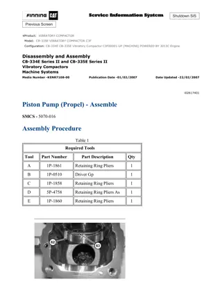
Caterpillar Cat CS-433E, CP-433E Vibratory Compactor (Prefix BTY) Service Repair Manual Instant Download
Please open the website below to get the complete manualnn//
Download Presentation

Please find below an Image/Link to download the presentation.
The content on the website is provided AS IS for your information and personal use only. It may not be sold, licensed, or shared on other websites without obtaining consent from the author. Download presentation by click this link. If you encounter any issues during the download, it is possible that the publisher has removed the file from their server.
E N D
Presentation Transcript
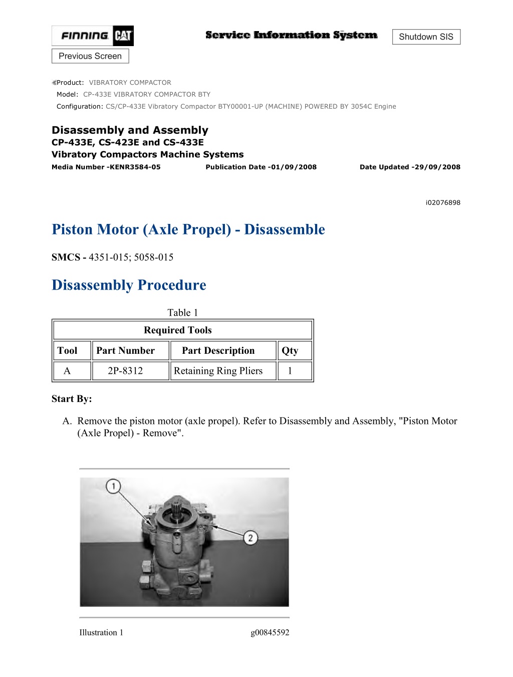
CS/CP-433E Vibratory Compactor BTY00001-UP (MACHINE) POWERED BY 3054... 1/9 Shutdown SIS Previous Screen Product: VIBRATORY COMPACTOR Model: CP-433E VIBRATORY COMPACTOR BTY Configuration: CS/CP-433E Vibratory Compactor BTY00001-UP (MACHINE) POWERED BY 3054C Engine Disassembly and Assembly CP-433E, CS-423E and CS-433E Vibratory Compactors Machine Systems Media Number -KENR3584-05 Publication Date -01/09/2008 Date Updated -29/09/2008 i02076898 Piston Motor (Axle Propel) - Disassemble SMCS - 4351-015; 5058-015 Disassembly Procedure Table 1 Required Tools Tool Part Number Part Description Qty A 2P-8312 Retaining Ring Pliers 1 Start By: A. Remove the piston motor (axle propel). Refer to Disassembly and Assembly, "Piston Motor (Axle Propel) - Remove". Illustration 1 g00845592 https://127.0.0.1/sisweb/sisweb/techdoc/techdoc_print_page.jsp?returnurl=/sis... 2021/4/25
CS/CP-433E Vibratory Compactor BTY00001-UP (MACHINE) POWERED BY 3054... 2/9 1. Remove bolts (1) and front cover (2) from the housing. Remove the gasket from the housing. Illustration 2 g00845593 2. Remove retaining ring (3) and lip type seal (4) from front cover (2) . Illustration 3 g00845594 3. Remove retaining ring (5). Remove the bearing and shaft (6) as a unit from front cover (2) . https://127.0.0.1/sisweb/sisweb/techdoc/techdoc_print_page.jsp?returnurl=/sis... 2021/4/25
CS/CP-433E Vibratory Compactor BTY00001-UP (MACHINE) POWERED BY 3054... 3/9 Illustration 4 g00845596 4. Remove retaining rings (7) from shaft (6). Use a suitable press and remove bearing (8) from shaft (6) . Illustration 5 g00845598 5. Put identification marks on journal bearings (10) for installation purposes. Remove journal bearings (10) from front cover (2). Remove spring pins (9) from the front cover. Illustration 6 g00845599 https://127.0.0.1/sisweb/sisweb/techdoc/techdoc_print_page.jsp?returnurl=/sis... 2021/4/25
https://www.ebooklibonline.com Hello dear friend! Thank you very much for reading. Enter the link into your browser. The full manual is available for immediate download. https://www.ebooklibonline.com
CS/CP-433E Vibratory Compactor BTY00001-UP (MACHINE) POWERED BY 3054... 4/9 Illustration 7 g00845600 Improper assembly of parts that are spring loaded can cause bodily injury. To prevent possible injury, follow the established assembly procedure and wear protective equipment. 6. Remove bolts (12) and cover (14) from the housing. Remove the gasket from the cover. 7. Remove bolts (11) and cover (17) from the housing. Remove gasket (17) from the cover. 8. Remove spring (15) and stop (16) from the servo piston. Illustration 8 g00845601 https://127.0.0.1/sisweb/sisweb/techdoc/techdoc_print_page.jsp?returnurl=/sis... 2021/4/25
CS/CP-433E Vibratory Compactor BTY00001-UP (MACHINE) POWERED BY 3054... 5/9 NOTICE Do not turn the housing upside down to remove the swashplate from the housing. 9. Remove sleeve bearing (18) and swashplate (19) from the housing. Illustration 9 g00845602 NOTICE Sleeve bearing (18) must be reinstalled in the original position on swashplate (19) . 10. Note the position of sleeve bearing (18) on swashplate (19). Remove sleeve bearing (18) and pin (20) from swashplate (19) . https://127.0.0.1/sisweb/sisweb/techdoc/techdoc_print_page.jsp?returnurl=/sis... 2021/4/25
CS/CP-433E Vibratory Compactor BTY00001-UP (MACHINE) POWERED BY 3054... 6/9 Illustration 10 g00845603 11. Use Tool (A) to remove cylinder block assembly (21) from housing (22) . Illustration 11 g00845604 12. Remove piston assemblies (23) and slipper guide (24) from cylinder block (25) . Illustration 12 g00845606 13. Remove retainer guide (26) from cylinder block (25) . https://127.0.0.1/sisweb/sisweb/techdoc/techdoc_print_page.jsp?returnurl=/sis... 2021/4/25
CS/CP-433E Vibratory Compactor BTY00001-UP (MACHINE) POWERED BY 3054... 7/9 Illustration 13 g00845607 14. Remove pin retainer (27) and pins (28) from cylinder block (25) . Illustration 14 g00845608 Possible injury can result when removing the retaining ring and spring. Spring force will be released when the retaining ring is removed. Be prepared to hold the cylinder assembly as the retaining ring is removed. 15. Put cylinder block (25) in a press. Install a suitable piece of square steel stock against washer (30). Put slight compression on washer (30) with the press. Remove retaining ring (29) and slowly release the spring compression. 16. Remove washer (30), spring (31), and washer (32) from cylinder block (25) . https://127.0.0.1/sisweb/sisweb/techdoc/techdoc_print_page.jsp?returnurl=/sis... 2021/4/25
CS/CP-433E Vibratory Compactor BTY00001-UP (MACHINE) POWERED BY 3054... 8/9 Illustration 15 g00845609 17. Put identification marks on valve plate (34) and locating pin (33) from installation purposes. Remove valve plate (34) and locating pin (33) from the housing. 18. Remove needle bearing (35) from the housing. Illustration 16 g00845610 19. Remove the servo piston (36) from housing (22) . https://127.0.0.1/sisweb/sisweb/techdoc/techdoc_print_page.jsp?returnurl=/sis... 2021/4/25
CS/CP-433E Vibratory Compactor BTY00001-UP (MACHINE) POWERED BY 3054... 9/9 Illustration 17 g00845611 20. Remove piston rings (37) and the O-rings from the outer groove. Remove bearings (38) from the inner groove. Illustration 18 g00845613 Sudden release of spring force can cause injury. To prevent the possibility of injury, follow the procedure to relieve the spring pressure. 21. Remove plug (46), spring (45), and poppet (43) from the housing. Remove the shims and the O-ring seal from plug (46) . 22. Remove plug (41) and spring (44) from both sides of the housing. Remove the O-ring seal from each plug (41) . 23. Remove spring guide (40), valve spool (39), and spring guide (42) from the housing. Copyright 1993 - 2021 Caterpillar Inc. Sun Apr 25 22:39:19 UTC+0800 2021 All Rights Reserved. Private Network For SIS Licensees. https://127.0.0.1/sisweb/sisweb/techdoc/techdoc_print_page.jsp?returnurl=/sis... 2021/4/25
CS/CP-433E Vibratory Compactor BTY00001-UP (MACHINE) POWERED BY 3054... 1/8 Shutdown SIS Previous Screen Product: VIBRATORY COMPACTOR Model: CP-433E VIBRATORY COMPACTOR BTY Configuration: CS/CP-433E Vibratory Compactor BTY00001-UP (MACHINE) POWERED BY 3054C Engine Disassembly and Assembly CP-433E, CS-423E and CS-433E Vibratory Compactors Machine Systems Media Number -KENR3584-05 Publication Date -01/09/2008 Date Updated -29/09/2008 i02076912 Piston Motor (Axle Propel) - Assemble SMCS - 4351-016; 5058-016 Assembly Procedure Table 1 Required Tools Tool Part Number Part Description Qty A 2P-8312 Retaining Ring Pliers 1 1. Inspect all parts and clean all parts. If any parts are worn or damaged, use new Caterpillar parts for replacement. 2. Inspect all seals. Damaged seals must be replaced. Use new Caterpillar seals for replacement. Illustration 1 g00845613 https://127.0.0.1/sisweb/sisweb/techdoc/techdoc_print_page.jsp?returnurl=/sis... 2021/4/25
CS/CP-433E Vibratory Compactor BTY00001-UP (MACHINE) POWERED BY 3054... 2/8 3. Install spring guides (40) and (42) on valve spool (39). Install the valve spool in housing (22) . 4. Install the O-ring seal on both plugs (41). Install both springs (44) and both plugs (41) in the housing. 5. Install the O-ring seal on plug (46). Install the shims on the plug. Install poppet (43), spring (45), and plug (46) in the housing. Illustration 2 g00845611 Illustration 3 g00845610 6. Install bearings (38) in the inner grooves of servo piston (36). Install O-rings and piston rings (37) in the inner groove of servo piston (36) . 7. Install servo piston (36) in the housing. https://127.0.0.1/sisweb/sisweb/techdoc/techdoc_print_page.jsp?returnurl=/sis... 2021/4/25
CS/CP-433E Vibratory Compactor BTY00001-UP (MACHINE) POWERED BY 3054... 3/8 Illustration 4 g00845609 8. Install needle bearing (35) in housing (22). Install the needle bearing 2.2 .2 mm (0.09 0.008 inch) above the inside surface of the housing. 9. Install locating pin (33) in the housing. Install the locating pin 4.52 .23 mm (0.170 0.01 inch) above the inside surface of the housing. 10. Install valve plate (34) in the housing. The bronze side of the valve plate must be visible inside the housing. The notch on the valve plate must engage locating pin (33) . Illustration 5 g00845608 11. Install washer (32), spring (31), and washer (30) in cylinder block (25). Put the cylinder block in a press. Install a suitable piece of square steel stock against washer (30). Compress spring (31) and install retaining ring (29). Slowly release the spring compression. https://127.0.0.1/sisweb/sisweb/techdoc/techdoc_print_page.jsp?returnurl=/sis... 2021/4/25
CS/CP-433E Vibratory Compactor BTY00001-UP (MACHINE) POWERED BY 3054... 4/8 Illustration 6 g00845607 12. Install pins (28) and pin retainer (27) in cylinder block (25) . Illustration 7 g00845606 13. Install retainer guide (26) on cylinder block (25) . Illustration 8 g00845604 https://127.0.0.1/sisweb/sisweb/techdoc/techdoc_print_page.jsp?returnurl=/sis... 2021/4/25
CS/CP-433E Vibratory Compactor BTY00001-UP (MACHINE) POWERED BY 3054... 5/8 14. Install piston assemblies (23) in slipper guide (24). Install the piston assemblies and slipper guide in the cylinder block. Illustration 9 g00845603 15. Use Tool (A) to install cylinder block assembly (21) in housing (22) . Illustration 10 g00845602 16. Install pin (20) in swashplate (19). Install sleeve bearing (18) on pin (20). The notched side of the sleeve bearing must face the convex portion of the swashplate. https://127.0.0.1/sisweb/sisweb/techdoc/techdoc_print_page.jsp?returnurl=/sis... 2021/4/25
CS/CP-433E Vibratory Compactor BTY00001-UP (MACHINE) POWERED BY 3054... 6/8 Illustration 11 g00845601 17. Install sleeve bearing (18) and swashplate (19) in the housing. Illustration 12 g00845600 Illustration 13 g00845599 18. Install spring (15) and stop (16) in the servo piston. https://127.0.0.1/sisweb/sisweb/techdoc/techdoc_print_page.jsp?returnurl=/sis... 2021/4/25
CS/CP-433E Vibratory Compactor BTY00001-UP (MACHINE) POWERED BY 3054... 7/8 19. Install gasket (17), cover (13), and bolts (11). Install the gasket, cover (14), and bolts (12). Tighten the bolts to a torque of 16 3 N m (12 2 lb ft). Illustration 14 g00845598 20. Install spring pins (9) in front cover (2) . 21. Install journal bearings (10) on the front cover and spring pins (9) . Illustration 15 g00845596 22. Install lower retaining ring (7) on shaft (6). Use a press and install bearing (8) on shaft (6). Install upper retaining ring (7) . https://127.0.0.1/sisweb/sisweb/techdoc/techdoc_print_page.jsp?returnurl=/sis... 2021/4/25
CS/CP-433E Vibratory Compactor BTY00001-UP (MACHINE) POWERED BY 3054... 8/8 Illustration 16 g00845594 23. Install shaft (6) in front cover (2) and install retaining ring (5) . Illustration 17 g00845970 24. Position the gasket on the housing and install front cover (2). Install seven bolts (1) . 25. Install lip type seal (4) and install retaining ring (3) . End By: Install the piston motor (axle propel). Refer to Disassembly and Assembly, "Piston Motor (Axle Propel) - Install". Copyright 1993 - 2021 Caterpillar Inc. Sun Apr 25 22:40:15 UTC+0800 2021 All Rights Reserved. Private Network For SIS Licensees. https://127.0.0.1/sisweb/sisweb/techdoc/techdoc_print_page.jsp?returnurl=/sis... 2021/4/25
CS/CP-433E Vibratory Compactor BTY00001-UP (MACHINE) POWERED BY 3054... 1/1 Shutdown SIS Previous Screen Product: VIBRATORY COMPACTOR Model: CP-433E VIBRATORY COMPACTOR BTY Configuration: CS/CP-433E Vibratory Compactor BTY00001-UP (MACHINE) POWERED BY 3054C Engine Disassembly and Assembly CP-433E, CS-423E and CS-433E Vibratory Compactors Machine Systems Media Number -KENR3584-05 Publication Date -01/09/2008 Date Updated -29/09/2008 i02076986 Piston Motor (Axle Propel) - Install SMCS - 4351-012; 5058-012 Installation Procedure Illustration 1 g00837607 1. Install axle propel motor (1) and bolts (3). The weight of the axle propel motor is approximately 24 kg (52 lb). 2. Connect hose assemblies (2) on axle propel motor (1) . Copyright 1993 - 2021 Caterpillar Inc. Sun Apr 25 22:41:11 UTC+0800 2021 All Rights Reserved. Private Network For SIS Licensees. https://127.0.0.1/sisweb/sisweb/techdoc/techdoc_print_page.jsp?returnurl=/sis... 2021/4/25
CS/CP-433E Vibratory Compactor BTY00001-UP (MACHINE) POWERED BY 3054... 1/2 Shutdown SIS Previous Screen Product: VIBRATORY COMPACTOR Model: CP-433E VIBRATORY COMPACTOR BTY Configuration: CS/CP-433E Vibratory Compactor BTY00001-UP (MACHINE) POWERED BY 3054C Engine Disassembly and Assembly CP-433E, CS-423E and CS-433E Vibratory Compactors Machine Systems Media Number -KENR3584-05 Publication Date -01/09/2008 Date Updated -29/09/2008 i02085896 Wheel and Tire - Remove and Install SMCS - 4202-010; 4208-010 Removal Procedure Table 1 Required Tools Tool Part Number Part Description Qty A 180-3033 Stand 2 1. Engage the parking brake. Place wooden wedges in front of the drum assembly and behind the drum assembly. Illustration 1 g00827930 2. Raise the rear of the machine until the tires are off the floor. Install Tooling (A) under the front of the rear frame of the machine, as shown. https://127.0.0.1/sisweb/sisweb/techdoc/techdoc_print_page.jsp?returnurl=/sis... 2021/4/25
CS/CP-433E Vibratory Compactor BTY00001-UP (MACHINE) POWERED BY 3054... 2/2 3. Remove lug nuts (2). Use two persons in order to remove the wheel and tire assembly (1). The weight of the wheel and tire assembly is 100 kg (220 lb). 4. Repeat Step 3 in order to remove the other wheel and tire assembly. Installation Procedure 1. Check the condition of the wheel studs. If the studs are damaged use new Caterpillar parts for replacement. Illustration 2 g00827930 2. Use two persons in order to install the wheel and tire assembly (2). Install lug nuts (1). Tighten the lug nuts to a torque of 530 70 N m (390 51 lb ft). 3. Repeat Step 2 in order to install the other wheel and tire assembly. 4. Raise the rear of the machine. Remove Tooling (A) and lower the machine. Copyright 1993 - 2021 Caterpillar Inc. Sun Apr 25 22:42:06 UTC+0800 2021 All Rights Reserved. Private Network For SIS Licensees. https://127.0.0.1/sisweb/sisweb/techdoc/techdoc_print_page.jsp?returnurl=/sis... 2021/4/25
CS/CP-433E Vibratory Compactor BTY00001-UP (MACHINE) POWERED BY 3054... 1/3 Shutdown SIS Previous Screen Product: VIBRATORY COMPACTOR Model: CP-433E VIBRATORY COMPACTOR BTY Configuration: CS/CP-433E Vibratory Compactor BTY00001-UP (MACHINE) POWERED BY 3054C Engine Disassembly and Assembly CP-433E, CS-423E and CS-433E Vibratory Compactors Machine Systems Media Number -KENR3584-05 Publication Date -01/09/2008 Date Updated -29/09/2008 i02071464 Axle - Remove SMCS - 3260-011; 3278-011 Removal Procedure Table 1 Required Tools Tool Part Number Part Description Qty 6V-3145 Load Leveling Beam 1 A 138-7574 Link Brackets 2 6V-9507 Face Seal Plug (9/16 - 18 THD) 1 6V-9828 Cap Assembly (9/16 - 18 THD) 1 6V-9509 Face Seal Plug (13/16 - 16 THD) 2 ZZ 6V-9830 Cap Assembly (13/16 - 16 THD) 2 6V-9511 Face Seal Plug (1 3/16 - 12 THD) 2 6V-9832 Cap Assembly (1 3/16 - 12 THD) 2 Start By: A. Remove the wheel and tire assemblies. Refer to Disassembly and Assembly, "Wheel and Tire - Remove and Install". Note: SERVICE DATA: TOOLING (ZZ) WILL NOT BE IDENTIFIED IN PHOTOGRAPHS IN THE REMOVAL OR THE INSTALLATION. THIS TOOLING IS SHOWN IN ORDER TO ASSIST THE EXPERIENCED SERVICEMAN. https://127.0.0.1/sisweb/sisweb/techdoc/techdoc_print_page.jsp?returnurl=/sis... 2021/4/25
CS/CP-433E Vibratory Compactor BTY00001-UP (MACHINE) POWERED BY 3054... 2/3 Personal injury can result from hydraulic oil pressure and hot oil. Hydraulic oil pressure can remain in the hydraulic system after the engine has been stopped. Serious injury can be caused if this pressure is not released before any service is done on the hydraulic system. Make sure all of the work tools have been lowered to the ground, and the oil is cool before removing any components or lines. Remove the oil filler cap only when the engine is stopped, and the filler cap is cool enough to touch with your bare hand. NOTICE Care must be taken to ensure that fluids are contained during performance of inspection, maintenance, testing, adjusting, and repair of the machine. Be prepared to collect the fluid with suitable containers before opening any compartment or disassembling any component containing fluids. Refer to Special Publication, NENG2500, "Caterpillar Tools and Shop Products Guide"for tools and supplies to collect and contain fluids in Caterpillar machines. Dispose of all fluids according to local regulations. Note: Put identification marks on all lines, on all hoses, on all wires, and on all tubes for installation purposes. Plug all lines, hoses, and tubes. This helps to prevent fluid loss and this helps to keep contaminants from entering the system. https://127.0.0.1/sisweb/sisweb/techdoc/techdoc_print_page.jsp?returnurl=/sis... 2021/4/25
CS/CP-433E Vibratory Compactor BTY00001-UP (MACHINE) POWERED BY 3054... 3/3 Illustration 1 g00827998 1. Disconnect hose assemblies (1) from axle propel motor (2) . Illustration 2 g00827999 2. Attach a suitable lifting device and Tooling (A) to axle (3) . Illustration 3 g00828002 3. Remove bolts (4) and plate (5) from each side and remove the axle from the machine. The weight of the axle that is equipped without brakes is approximately 300 kg (650 lb). The weight of the axle that is equipped with brakes is approximately 400 kg (875 lb). Copyright 1993 - 2021 Caterpillar Inc. Sun Apr 25 22:43:02 UTC+0800 2021 All Rights Reserved. Private Network For SIS Licensees. https://127.0.0.1/sisweb/sisweb/techdoc/techdoc_print_page.jsp?returnurl=/sis... 2021/4/25
CS/CP-433E Vibratory Compactor BTY00001-UP (MACHINE) POWERED BY 3054... 1/11 Shutdown SIS Previous Screen Product: VIBRATORY COMPACTOR Model: CP-433E VIBRATORY COMPACTOR BTY Configuration: CS/CP-433E Vibratory Compactor BTY00001-UP (MACHINE) POWERED BY 3054C Engine Disassembly and Assembly CP-433E, CS-423E and CS-433E Vibratory Compactors Machine Systems Media Number -KENR3584-05 Publication Date -01/09/2008 Date Updated -29/09/2008 i02070626 Axle (without Brakes) - Disassemble SMCS - 3260-015; 3278-015 Disassembly Procedure Table 1 Required Tools Tool Part Number Part Description Qty A 8H-0700 Bearing Puller 1 B 1P-1859 Retaining Ring Pliers 1 C 1P-0510 Driver Gp 1 D 154-6182 Forcing Bolt 2 E 138-7573 Link Bracket 2 Start By: A. Remove the axle. Refer to Disassembly and Assembly, "Axle - Remove". 1. Drain the oil from the differential into a suitable container. The capacity of the differential is approximately 9 L (2.4 US gal). https://127.0.0.1/sisweb/sisweb/techdoc/techdoc_print_page.jsp?returnurl=/sis... 2021/4/25
CS/CP-433E Vibratory Compactor BTY00001-UP (MACHINE) POWERED BY 3054... 2/11 Illustration 1 g00847459 2. Drain the oil from the gearbox into a suitable container. The capacity of the gearbox is approximately 1.2 L (0.3 US gal). 3. Remove the bolts and the propel motor from the gearbox. Install the cover and the bolts on the gearbox. 4. Remove bolts (1) and cover (2) . Illustration 2 g00847460 5. Remove O-ring seal (3) from cover (2) . https://127.0.0.1/sisweb/sisweb/techdoc/techdoc_print_page.jsp?returnurl=/sis... 2021/4/25
CS/CP-433E Vibratory Compactor BTY00001-UP (MACHINE) POWERED BY 3054... 3/11 Illustration 3 g00847461 6. Remove bolts (4) and cover (5) . Illustration 4 g00847462 7. Remove dowels (6) from cover (5) . Illustration 5 g00847463 8. Remove gear (6) and gear (7) . https://127.0.0.1/sisweb/sisweb/techdoc/techdoc_print_page.jsp?returnurl=/sis... 2021/4/25
CS/CP-433E Vibratory Compactor BTY00001-UP (MACHINE) POWERED BY 3054... 4/11 Illustration 6 g00847464 9. Use Tooling (A) and remove bearing (8) from gear (7) . Illustration 7 g00847465 10. Use Tooling (A) and remove bearing (9) from gear (7) . https://127.0.0.1/sisweb/sisweb/techdoc/techdoc_print_page.jsp?returnurl=/sis... 2021/4/25
CS/CP-433E Vibratory Compactor BTY00001-UP (MACHINE) POWERED BY 3054... 5/11 Illustration 8 g00847466 11. Use Tooling (A) and remove bearing (10) from gear (6) . Illustration 9 g00847467 12. Use Tooling (B) to remove retaining ring (11). Use Tooling (A) and remove bearing (12) from gear (6) . Illustration 10 g00847468 13. Remove bolts (13) and remove cover (14) . https://127.0.0.1/sisweb/sisweb/techdoc/techdoc_print_page.jsp?returnurl=/sis... 2021/4/25
CS/CP-433E Vibratory Compactor BTY00001-UP (MACHINE) POWERED BY 3054... 6/11 Illustration 11 g00847469 14. Drain the oil from the wheel hub into a suitable container. The capacity of the wheel hub is approximately 1.3 L (0.3 US gal). 15. Remove screws (15) and end cover (16) . Illustration 12 g00847471 16. Remove bolts (17), washers (18), gears (19), and the 84 needle bearings. https://127.0.0.1/sisweb/sisweb/techdoc/techdoc_print_page.jsp?returnurl=/sis... 2021/4/25
CS/CP-433E Vibratory Compactor BTY00001-UP (MACHINE) POWERED BY 3054... 7/11 Illustration 13 g01064656 17. Remove O-ring seal (20) from ring gear (23) . 18. Remove shaft (21) . 19. Remove bolts (22) . Illustration 14 g01064989 20. Install bolts (22) to ring gear (23), as shown. Turn the bolts evenly in order to remove the sun gear. Illustration 15 g01064990 21. Use a suitable press and remove bushings (24) from ring gear (23) . https://127.0.0.1/sisweb/sisweb/techdoc/techdoc_print_page.jsp?returnurl=/sis... 2021/4/25
Suggest: If the above button click is invalid. Please download this document first, and then click the above link to download the complete manual. Thank you so much for reading
CS/CP-433E Vibratory Compactor BTY00001-UP (MACHINE) POWERED BY 3054... 8/11 Illustration 16 g01061619 Illustration 17 g01061625 22. Remove bearing cone (26), hub (25), and bearing cone (27) . Illustration 18 g01061629 23. Remove lip seal (28) and bearing cups (29) from hub (25) . 24. Repeat Steps 14 through 23 in order to disassemble the other wheel hub. https://127.0.0.1/sisweb/sisweb/techdoc/techdoc_print_page.jsp?returnurl=/sis... 2021/4/25
https://www.ebooklibonline.com Hello dear friend! Thank you very much for reading. Enter the link into your browser. The full manual is available for immediate download. https://www.ebooklibonline.com

