Caterpillar Cat CB-334E, CB-335E Vibratory Compactor (Prefix C5J) Service Repair Manual Instant Download
Please open the website below to get the complete manualnn//

Download Presentation

Please find below an Image/Link to download the presentation.
The content on the website is provided AS IS for your information and personal use only. It may not be sold, licensed, or shared on other websites without obtaining consent from the author. Download presentation by click this link. If you encounter any issues during the download, it is possible that the publisher has removed the file from their server.
E N D
Presentation Transcript
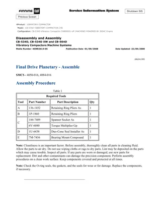
CB-334E,CB-335E Vibratory Compactor C5J00001-UP (MACHINE) POWERED BY... 1/2 Shutdown SIS Previous Screen Product: VIBRATORY COMPACTOR Model: CB-335E VIBRATORY COMPACTOR C5J Configuration: CB-334E,CB-335E Vibratory Compactor C5J00001-UP (MACHINE) POWERED BY 3013C Engine Disassembly and Assembly 3003, 3013, 3014 and 3024 Engines for Caterpillar Built Machines Media Number -SENR5027-05 Publication Date -01/05/2005 Date Updated -16/05/2005 i01638277 Crankshaft Rear Seal - Remove SMCS - 1161-011 Removal Procedure Start By: A. Remove the flywheel housing. Refer to Disassembly and Assembly, "Flywheel Housing - Remove and Install". NOTICE Keep all parts clean from contaminants. Contaminants may cause rapid wear and shortened component life. NOTICE Care must be taken to ensure that fluids are contained during performance of inspection, maintenance, testing, adjusting and repair of the product. Be prepared to collect the fluid with suitable containers before opening any compartment or disassembling any component containing fluids. Refer to Special Publication, NENG2500, "Caterpillar Tools and Shop Products Guide" for tools and supplies suitable to collect and contain fluids on Caterpillar products. Dispose of all fluids according to local regulations and mandates. https://127.0.0.1/sisweb/sisweb/techdoc/techdoc_print_page.jsp?returnurl=/sis... 2021/8/21
CB-334E,CB-335E Vibratory Compactor C5J00001-UP (MACHINE) POWERED BY... 2/2 Illustration 1 g00847841 1. Remove bolts (3) and backplate (2) from the rear of the cylinder block. 2. Remove crankshaft rear seal (1) from the cylinder block. Copyright 1993 - 2021 Caterpillar Inc. Sat Aug 21 23:07:10 UTC+0800 2021 All Rights Reserved. Private Network For SIS Licensees. https://127.0.0.1/sisweb/sisweb/techdoc/techdoc_print_page.jsp?returnurl=/sis... 2021/8/21
CB-334E,CB-335E Vibratory Compactor C5J00001-UP (MACHINE) POWERED BY... 1/2 Shutdown SIS Previous Screen Product: VIBRATORY COMPACTOR Model: CB-335E VIBRATORY COMPACTOR C5J Configuration: CB-334E,CB-335E Vibratory Compactor C5J00001-UP (MACHINE) POWERED BY 3013C Engine Disassembly and Assembly 3003, 3013, 3014 and 3024 Engines for Caterpillar Built Machines Media Number -SENR5027-05 Publication Date -01/05/2005 Date Updated -16/05/2005 i01099295 Crankshaft Rear Seal - Install SMCS - 1161-012 Installation Procedure NOTICE Keep all parts clean from contaminants. Contaminants may cause rapid wear and shortened component life. 1. Clean the back of the cylinder block and the mating surface of the backplate. Illustration 1 g00578148 2. Install crankshaft rear seal (3) on the cylinder block. https://127.0.0.1/sisweb/sisweb/techdoc/techdoc_print_page.jsp?returnurl=/sis... 2021/8/21
https://www.ebooklibonline.com Hello dear friend! Thank you very much for reading. Enter the link into your browser. The full manual is available for immediate download. https://www.ebooklibonline.com
CB-334E,CB-335E Vibratory Compactor C5J00001-UP (MACHINE) POWERED BY... 2/2 3. Put a bead of 4C-9612 Silicone Sealant around the bolt holes and the face of the cylinder block. Illustration 2 g00578100 4. Position backplate (2) on the rear of the engine. 5. Install bolts (1) that fasten backplate (2) on the engine. Tighten the bolts to the following torque: 3003 Engine ... 50 N m (37 lb ft) 3013, 3014 and 3024 Engines ... 15 N m (11 lb ft) End By: Install the flywheel housing. Refer to Disassembly and Assembly, "Flywheel Housing - Remove and Install". Copyright 1993 - 2021 Caterpillar Inc. Sat Aug 21 23:08:06 UTC+0800 2021 All Rights Reserved. Private Network For SIS Licensees. https://127.0.0.1/sisweb/sisweb/techdoc/techdoc_print_page.jsp?returnurl=/sis... 2021/8/21
CB-334E,CB-335E Vibratory Compactor C5J00001-UP (MACHINE) POWERED BY... 1/7 Shutdown SIS Previous Screen Product: VIBRATORY COMPACTOR Model: CB-335E VIBRATORY COMPACTOR C5J Configuration: CB-334E,CB-335E Vibratory Compactor C5J00001-UP (MACHINE) POWERED BY 3013C Engine Disassembly and Assembly 3003, 3013, 3014 and 3024 Engines for Caterpillar Built Machines Media Number -SENR5027-05 Publication Date -01/05/2005 Date Updated -16/05/2005 i01429119 Flywheel Housing - Remove and Install SMCS - 1157-010 Removal Procedure ( 3003 Engine) Start By: A. Remove the electric starting motor. Refer to Disassembly and Assembly, "Electric Starting Motor - Remove and Install". NOTICE Keep all parts clean from contaminants. Contaminants may cause rapid wear and shortened component life. 1. Support the engine with blocks or a suitable lifting device on a flat surface. https://127.0.0.1/sisweb/sisweb/techdoc/techdoc_print_page.jsp?returnurl=/sis... 2021/8/21
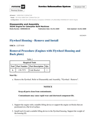
CB-334E,CB-335E Vibratory Compactor C5J00001-UP (MACHINE) POWERED BY... 2/7 Illustration 1 g00585274 2. Remove two bolts (2) that fasten the flywheel housing to the backplate. 3. Remove two bolts (3) that fasten the backplate to the flywheel housing. 4. Remove flywheel housing (1) from the rear of the engine. Installation Procedure ( 3003 Engine) NOTICE Keep all parts clean from contaminants. Contaminants may cause rapid wear and shortened component life. Illustration 2 g00585274 1. Position flywheel housing (1) on the rear of engine. 2. Install two bolts (3) that fasten the backplate to the flywheel housing. 3. Install two bolts (2) that fasten the flywheel housing to the backplate. Tighten the flywheel housing bolts for the 3003 engine to the following torque: ... 50 N m (37 lb ft) End By: Install the electric starting motor. Refer to Disassembly and Assembly, "Electric Starting Motor - Remove and Install". Removal Procedure ( 3013, 3014 and 3024 Engines) Table 1 https://127.0.0.1/sisweb/sisweb/techdoc/techdoc_print_page.jsp?returnurl=/sis... 2021/8/21
CB-334E,CB-335E Vibratory Compactor C5J00001-UP (MACHINE) POWERED BY... 3/7 Required Tools Tool Part Number Part Description Qty A 138-7573 Link Bracket 1 Start By: A. Remove the flywheel. Refer to Disassembly and Assembly, "Flywheel - Remove". NOTICE Keep all parts clean from contaminants. Contaminants may cause rapid wear and shortened component life. 1. Support the engine with blocks or a suitable lifting device on a flat level surface. Illustration 3 g00585650 2. Remove the bolt and clamp (1) in order to remove the hose and the clamp from the engine. https://127.0.0.1/sisweb/sisweb/techdoc/techdoc_print_page.jsp?returnurl=/sis... 2021/8/21
CB-334E,CB-335E Vibratory Compactor C5J00001-UP (MACHINE) POWERED BY... 4/7 Illustration 4 g00585658 3. Remove two bolts (2) that fasten the flywheel housing to the cylinder block. Illustration 5 g00585719 Illustration 6 g00585724 4. Install Tool (A) and a suitable lifting device on the flywheel housing. 5. Remove three bolts (4) on each side of the cylinder block. These bolts fasten the flywheel housing to the cylinder block. 6. Remove two bolts (3) that fasten the backplate to the flywheel housing. 7. Remove four nuts and four bolts (5) that fasten the backplate to flywheel housing (6) . https://127.0.0.1/sisweb/sisweb/techdoc/techdoc_print_page.jsp?returnurl=/sis... 2021/8/21
CB-334E,CB-335E Vibratory Compactor C5J00001-UP (MACHINE) POWERED BY... 5/7 Illustration 7 g00585878 8. Use a suitable lifting device to remove flywheel housing (6) from the cylinder block. The weight of the flywheel housing is 18 kg (40 lb). Installation Procedure ( 3013, 3014 and 3024 Engines) Table 2 Required Tools Tool Part Number Part Description Qty A 138-7573 Link Bracket 1 NOTICE Keep all parts clean from contaminants. Contaminants may cause rapid wear and shortened component life. 1. Clean the rear face of the cylinder block and the face of the flywheel housing. Inspect the dowels for damage. Replace the dowels, if necessary. https://127.0.0.1/sisweb/sisweb/techdoc/techdoc_print_page.jsp?returnurl=/sis... 2021/8/21
CB-334E,CB-335E Vibratory Compactor C5J00001-UP (MACHINE) POWERED BY... 6/7 Illustration 8 g00585878 2. Align flywheel housing (6) on the dowels that are on the rear of the cylinder block. Illustration 9 g00585724 3. Install four nuts and four bolts (5) that fasten the backplate to flywheel housing (6) . Illustration 10 g00585719 4. Install two bolts (3) that fasten the backplate to the flywheel housing. https://127.0.0.1/sisweb/sisweb/techdoc/techdoc_print_page.jsp?returnurl=/sis... 2021/8/21
CB-334E,CB-335E Vibratory Compactor C5J00001-UP (MACHINE) POWERED BY... 7/7 5. Install three bolts (4) on each side of the cylinder block. These bolts fasten the flywheel housing to the cylinder block. 6. Tighten the flywheel housing bolts to the following torque: 3013, 3014, and 3024 Engines ... 25 N m (18 lb ft) 7. Remove Tool (A) from the flywheel housing. Illustration 11 g00585658 8. Install two bolts (2) that fasten the flywheel housing to the cylinder block. Illustration 12 g00585650 9. Put the hose in position and install the bolt and clamp (1) on the hose bracket. End By: Install the flywheel. Refer to Disassembly and Assembly, "Flywheel - Install". Copyright 1993 - 2021 Caterpillar Inc. Sat Aug 21 23:09:01 UTC+0800 2021 All Rights Reserved. Private Network For SIS Licensees. https://127.0.0.1/sisweb/sisweb/techdoc/techdoc_print_page.jsp?returnurl=/sis... 2021/8/21
CB-334E,CB-335E Vibratory Compactor C5J00001-UP (MACHINE) POWERED BY... 1/4 Shutdown SIS Previous Screen Product: VIBRATORY COMPACTOR Model: CB-335E VIBRATORY COMPACTOR C5J Configuration: CB-334E,CB-335E Vibratory Compactor C5J00001-UP (MACHINE) POWERED BY 3013C Engine Disassembly and Assembly 3003, 3013, 3014 and 3024 Engines for Caterpillar Built Machines Media Number -SENR5027-05 Publication Date -01/05/2005 Date Updated -16/05/2005 i01596029 Crankshaft Pulley - Remove and Install SMCS - 1205-010 Removal Procedure Table 1 Required Tools Tool Part Number Description Qty Puller Group (1) 8S-2264 1 A 6V-3668 Bolt (1) 3 ( 1 ) 3013, 3014 and 3024 Engines only 1. Loosen the bolts for the alternator and slide the alternator toward the engine. 2. Remove the fan drive belt. https://127.0.0.1/sisweb/sisweb/techdoc/techdoc_print_page.jsp?returnurl=/sis... 2021/8/21
CB-334E,CB-335E Vibratory Compactor C5J00001-UP (MACHINE) POWERED BY... 2/4 Illustration 1 g00827213 1. Remove nut (5) and washer (3) from crankshaft pulley (3) . Illustration 2 g00827241 https://127.0.0.1/sisweb/sisweb/techdoc/techdoc_print_page.jsp?returnurl=/sis... 2021/8/21
CB-334E,CB-335E Vibratory Compactor C5J00001-UP (MACHINE) POWERED BY... 3/4 2. Use Tool (A) in order to remove crankshaft pulley (2) from crankshaft (4) . Note: Remove crankshaft pulley (2) on 3013, 3014, and 3024 engines with Tooling (A) . 3. Remove woodruff key (1) from crankshaft (4) . Installation Procedure Illustration 3 g00827213 1. Install woodruff key (1) to crankshaft (4) . 2. Put crankshaft pulley (2) in position on the crankshaft (4) . 3. Position washer (3) on crankshaft (4) . 4. Lubricate nut (5) with clean engine oil and install the nut. 5. Tighten nut (5) to the following torque: 3003 Engine ... 123 N m (91 lb ft) 3013, 3014, 3024and 3024C Engines ... 304 N m (224 lb ft) 6. Put the V-belt in position on the engine. 7. Slide the alternator away from the engine and tighten the bolts for the alternator. Refer to Testing and Adjusting, "Belt Tension Chart" for more information on the proper belt tension. Copyright 1993 - 2021 Caterpillar Inc. Sat Aug 21 23:09:57 UTC+0800 2021 All Rights Reserved. https://127.0.0.1/sisweb/sisweb/techdoc/techdoc_print_page.jsp?returnurl=/sis... 2021/8/21
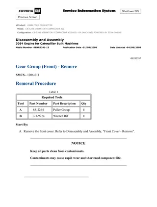
CB-334E,CB-335E Vibratory Compactor C5J00001-UP (MACHINE) POWERED BY... 1/3 Shutdown SIS Previous Screen Product: VIBRATORY COMPACTOR Model: CB-335E VIBRATORY COMPACTOR C5J Configuration: CB-334E,CB-335E Vibratory Compactor C5J00001-UP (MACHINE) POWERED BY 3013C Engine Disassembly and Assembly 3003, 3013, 3014 and 3024 Engines for Caterpillar Built Machines Media Number -SENR5027-05 Publication Date -01/05/2005 Date Updated -16/05/2005 i02006248 Crankshaft Front Seal - Remove SMCS - 1160-011 Removal Procedure Table 1 Required Tools Tool Part Number Part Description Qty A 1U-8145 Drill Bit 1 B 1U-7600 Slide Hammer Puller Gp 1 Start By: A. Remove the crankshaft pulley. Refer to Disassembly and Assembly, "Crankshaft Pulley - Remove and Install". NOTICE Keep all parts clean from contaminants. Contaminants may cause rapid wear and shortened component life. NOTICE Care must be taken to ensure that fluids are contained during performance of inspection, maintenance, testing, adjusting and repair of the product. Be prepared to collect the fluid with suitable containers https://127.0.0.1/sisweb/sisweb/techdoc/techdoc_print_page.jsp?returnurl=/sis... 2021/8/21
CB-334E,CB-335E Vibratory Compactor C5J00001-UP (MACHINE) POWERED BY... 2/3 before opening any compartment or disassembling any component containing fluids. Refer to Special Publication, NENG2500, "Caterpillar Tools and Shop Products Guide" for tools and supplies suitable to collect and contain fluids on Caterpillar products. Dispose of all fluids according to local regulations and mandates. Illustration 1 g00827263 1. Use Tooling (A) and carefully drill three evenly spaced holes (1) in crankshaft front seal (2) . https://127.0.0.1/sisweb/sisweb/techdoc/techdoc_print_page.jsp?returnurl=/sis... 2021/8/21
CB-334E,CB-335E Vibratory Compactor C5J00001-UP (MACHINE) POWERED BY... 3/3 Illustration 2 g01037807 2. Carefully remove the crankshaft front seal by alternating the position of Tooling (B) from one hole to another hole. This will allow you to evenly remove the crankshaft front seal from housing (3) . Note: Do not damage the flange of the crankshaft during the removal process of the crankshaft front seal. NOTICE Ensure that the main lip is used in order to remove the crankshaft front seal. Do not damage the edge of the housing for the crankshaft front seal. Copyright 1993 - 2021 Caterpillar Inc. Sat Aug 21 23:10:53 UTC+0800 2021 All Rights Reserved. Private Network For SIS Licensees. https://127.0.0.1/sisweb/sisweb/techdoc/techdoc_print_page.jsp?returnurl=/sis... 2021/8/21
CB-334E,CB-335E Vibratory Compactor C5J00001-UP (MACHINE) POWERED BY... 1/2 Shutdown SIS Previous Screen Product: VIBRATORY COMPACTOR Model: CB-335E VIBRATORY COMPACTOR C5J Configuration: CB-334E,CB-335E Vibratory Compactor C5J00001-UP (MACHINE) POWERED BY 3013C Engine Disassembly and Assembly 3003, 3013, 3014 and 3024 Engines for Caterpillar Built Machines Media Number -SENR5027-05 Publication Date -01/05/2005 Date Updated -16/05/2005 i02006359 Crankshaft Front Seal - Install SMCS - 1160-012 Installation Procedure Table 1 Required Tools Tool Part Number Part Description Qty C 5P-3537 Seal Guide 1 NOTICE Keep all parts clean from contaminants. Contaminants may cause rapid wear and shortened component life. https://127.0.0.1/sisweb/sisweb/techdoc/techdoc_print_page.jsp?returnurl=/sis... 2021/8/21
CB-334E,CB-335E Vibratory Compactor C5J00001-UP (MACHINE) POWERED BY... 2/2 Illustration 1 g01037829 1. Clean housing (3) for crankshaft front seal (2) and inspect the housing for any damage. 2. Lubricate the lip of crankshaft front seal (2) with clean engine oil. 3. Position crankshaft front seal (2) in housing (3) for the crankshaft front seal. NOTICE Ensure that the lip of the crankshaft front seal that is spring loaded is facing toward the inside of the front housing and that it is square with the bore of the housing for the crankshaft front seal. 4. Use Tooling (C) to install new crankshaft front seal (2) . 5. Apply clean engine oil on the area of the crankshaft pulley that will be in contact with crankshaft front seal (2) . End By: Install the crankshaft pulley. Refer to Disassembly and Assembly, "Crankshaft Pulley - Remove and Install". Copyright 1993 - 2021 Caterpillar Inc. Sat Aug 21 23:11:49 UTC+0800 2021 All Rights Reserved. Private Network For SIS Licensees. https://127.0.0.1/sisweb/sisweb/techdoc/techdoc_print_page.jsp?returnurl=/sis... 2021/8/21
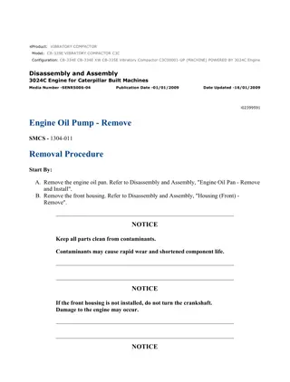
CB-334E,CB-335E Vibratory Compactor C5J00001-UP (MACHINE) POWERED BY... 1/3 Shutdown SIS Previous Screen Product: VIBRATORY COMPACTOR Model: CB-335E VIBRATORY COMPACTOR C5J Configuration: CB-334E,CB-335E Vibratory Compactor C5J00001-UP (MACHINE) POWERED BY 3013C Engine Disassembly and Assembly 3003, 3013, 3014 and 3024 Engines for Caterpillar Built Machines Media Number -SENR5027-05 Publication Date -01/05/2005 Date Updated -16/05/2005 i03631072 Housing (Front) - Remove SMCS - 1151-011 Removal Procedure Table 1 Required Tools Tool Part Number Part Description Qty 256-4866 or 256-4871 A Seal Installer 1 Start By: A. Remove the fuel injection pump. Refer to Disassembly and Assembly, "Fuel Injection Pump - Remove". B. Remove the crankshaft pulley. Refer to Disassembly and Assembly, "Crankshaft Pulley - Remove and Install". NOTICE Keep all parts clean from contaminants. Contaminants may cause rapid wear and shortened component life. NOTICE https://127.0.0.1/sisweb/sisweb/techdoc/techdoc_print_page.jsp?returnurl=/sis... 2021/8/21
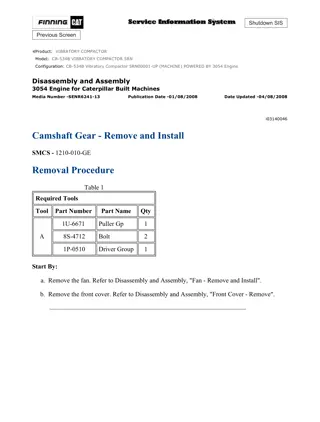
CB-334E,CB-335E Vibratory Compactor C5J00001-UP (MACHINE) POWERED BY... 2/3 If the front housing is not installed, do not turn the crankshaft. Damage to the engine may occur. NOTICE Care must be taken to ensure that fluids are contained during performance of inspection, maintenance, testing, adjusting and repair of the product. Be prepared to collect the fluid with suitable containers before opening any compartment or disassembling any component containing fluids. Refer to Special Publication, NENG2500, "Caterpillar Dealer Service Tool Catalog" for tools and supplies suitable to collect and contain fluids on Caterpillar products. Dispose of all fluids according to local regulations and mandates. Illustration 1 g01041799 1. Remove bolts (7) and nuts (6) from front housing (3) . 2. Install Tooling (A) before removing front housing (3) from cylinder block (1) . 3. Remove front housing (3) from the front of cylinder block (1) . Note: Ensure that mechanical stop lever (2) is in the full clockwise position before removing the front housing from cylinder block (1) . https://127.0.0.1/sisweb/sisweb/techdoc/techdoc_print_page.jsp?returnurl=/sis... 2021/8/21
CB-334E,CB-335E Vibratory Compactor C5J00001-UP (MACHINE) POWERED BY... 3/3 Note: Locating hole (4) and locating pin (5) must align for installation. 4. Remove gasket material from the cylinder block and remove gasket material from front housing (3) . 5. Inspect front housing (3) for wear or damage. If the front housing is damaged, use a new part for replacement. Copyright 1993 - 2021 Caterpillar Inc. Sat Aug 21 23:12:44 UTC+0800 2021 All Rights Reserved. Private Network For SIS Licensees. https://127.0.0.1/sisweb/sisweb/techdoc/techdoc_print_page.jsp?returnurl=/sis... 2021/8/21
CB-334E,CB-335E Vibratory Compactor C5J00001-UP (MACHINE) POWERED BY... 1/2 Shutdown SIS Previous Screen Product: VIBRATORY COMPACTOR Model: CB-335E VIBRATORY COMPACTOR C5J Configuration: CB-334E,CB-335E Vibratory Compactor C5J00001-UP (MACHINE) POWERED BY 3013C Engine Disassembly and Assembly 3003, 3013, 3014 and 3024 Engines for Caterpillar Built Machines Media Number -SENR5027-05 Publication Date -01/05/2005 Date Updated -16/05/2005 i03631073 Housing (Front) - Install SMCS - 1151-012 Installation Procedure Table 1 Required Tools Tool Part Number Part Description Qty 256-4866 or 256-4871 A Seal Installer 1 NOTICE Keep all parts clean from contaminants. Contaminants may cause rapid wear and shortened component life. NOTICE If the front housing is not installed, do not turn the crankshaft. Damage to the engine may occur. 1. Clean all surfaces thoroughly. Inspect the condition of the gasket. Replace the gasket, if necessary. https://127.0.0.1/sisweb/sisweb/techdoc/techdoc_print_page.jsp?returnurl=/sis... 2021/8/21
CB-334E,CB-335E Vibratory Compactor C5J00001-UP (MACHINE) POWERED BY... 2/2 2. Install Tooling (A) on the crankshaft. Illustration 1 g01041799 3. When front housing (3) is installed, rotate mechanical stop lever (2) in a clockwise direction for easier installation. Observe the position of the linkage (not shown) in the front housing. In order for the link to be connected during the fuel injection pump installation, correctly position the link for the fuel injection pump. 4. Align locating pin (5) with locating hole (4) on the oil pump cover. 5. Position front housing (3) on the front of cylinder block (1) . 6. Install bolts (7) and nuts (6) finger tight. Tighten bolts (7) and nuts (6) to a torque of 10 N m (89 lb in). 7. Remove Tooling (A) from the crankshaft. Note: Do not adjust the maximum fuel adjustment screw if the front housing or the governor linkage have been replaced. You must check the high idle rpm after assembly of the front housing. End By: a. Install the crankshaft pulley. Refer to Disassembly and Assembly, "Crankshaft Pulley - Remove and Install". b. Install the fuel injection pump. Refer to Disassembly and Assembly, "Fuel Injection Pump - Install". Copyright 1993 - 2021 Caterpillar Inc. Sat Aug 21 23:13:40 UTC+0800 2021 All Rights Reserved. Private Network For SIS Licensees. https://127.0.0.1/sisweb/sisweb/techdoc/techdoc_print_page.jsp?returnurl=/sis... 2021/8/21
CB-334E,CB-335E Vibratory Compactor C5J00001-UP (MACHINE) POWERED BY... 1/5 Shutdown SIS Previous Screen Product: VIBRATORY COMPACTOR Model: CB-335E VIBRATORY COMPACTOR C5J Configuration: CB-334E,CB-335E Vibratory Compactor C5J00001-UP (MACHINE) POWERED BY 3013C Engine Disassembly and Assembly 3003, 3013, 3014 and 3024 Engines for Caterpillar Built Machines Media Number -SENR5027-05 Publication Date -01/05/2005 Date Updated -16/05/2005 i01429179 Valve Mechanism Cover - Remove and Install SMCS - 1107-010 Removal Procedure ( 3003 Engine) NOTICE Keep all parts clean from contaminants. Contaminants may cause rapid wear and shortened component life. NOTICE Care must be taken to ensure that fluids are contained during performance of inspection, maintenance, testing, adjusting and repair of the product. Be prepared to collect the fluid with suitable containers before opening any compartment or disassembling any component containing fluids. Refer to Special Publication, NENG2500, "Caterpillar Tools and Shop Products Guide" for tools and supplies suitable to collect and contain fluids on Caterpillar products. Dispose of all fluids according to local regulations and mandates. Note: The inlet manifold that is used on 3013, 3014, and 3024 Engines is removable as a separate part. The inlet manifold on the 3003 Engine is part of the valve mechanism cover. https://127.0.0.1/sisweb/sisweb/techdoc/techdoc_print_page.jsp?returnurl=/sis... 2021/8/21
Suggest: If the above button click is invalid. Please download this document first, and then click the above link to download the complete manual. Thank you so much for reading
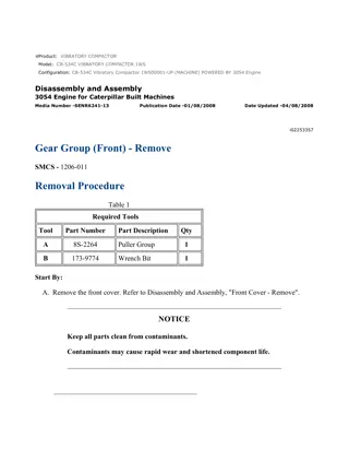
CB-334E,CB-335E Vibratory Compactor C5J00001-UP (MACHINE) POWERED BY... 2/5 Illustration 1 g00592619 1. Loosen clamp (1) and remove breather hose (2) from valve mechanism cover (3) . Illustration 2 g00592620 2. Remove three cap nuts (4) that fasten the valve mechanism cover to the engine. 3. Remove valve mechanism cover (3) and the gasket for the valve mechanism cover. Installation Procedure ( 3003 Engine) NOTICE Keep all parts clean from contaminants. Contaminants may cause rapid wear and shortened component life. https://127.0.0.1/sisweb/sisweb/techdoc/techdoc_print_page.jsp?returnurl=/sis... 2021/8/21
CB-334E,CB-335E Vibratory Compactor C5J00001-UP (MACHINE) POWERED BY... 3/5 1. Clean all surfaces thoroughly. Inspect the condition of the gasket for the valve mechanism cover. Replace the gasket, if necessary. Illustration 3 g00592620 2. Position the gasket for the valve mechanism cover on the cylinder head and install valve mechanism cover (3) . Note: Before you install three cap nuts (4), lubricate the threads with clean engine oil. 3. Install cap nuts (4) and tighten the nuts to a torque of 11 N m (8 lb ft). Illustration 4 g00592619 4. Install breather hose (2) and clamp (1) for the crankcase breather. Removal Procedure ( 3013, 3014, and 3024 Engines) NOTICE Keep all parts clean from contaminants. https://127.0.0.1/sisweb/sisweb/techdoc/techdoc_print_page.jsp?returnurl=/sis... 2021/8/21
https://www.ebooklibonline.com Hello dear friend! Thank you very much for reading. Enter the link into your browser. The full manual is available for immediate download. https://www.ebooklibonline.com
")
")
")

")
")
")
")
")
")
")
")
")
")
")
")
")
")
")
")
")
")
")
")
")
")

")
")