Caterpillar Cat CS-433E, CP-433E Vibratory Compactor (Prefix CFK) Service Repair Manual Instant Download
Please open the website below to get the complete manualnn// n
Download Presentation

Please find below an Image/Link to download the presentation.
The content on the website is provided AS IS for your information and personal use only. It may not be sold, licensed, or shared on other websites without obtaining consent from the author. Download presentation by click this link. If you encounter any issues during the download, it is possible that the publisher has removed the file from their server.
E N D
Presentation Transcript
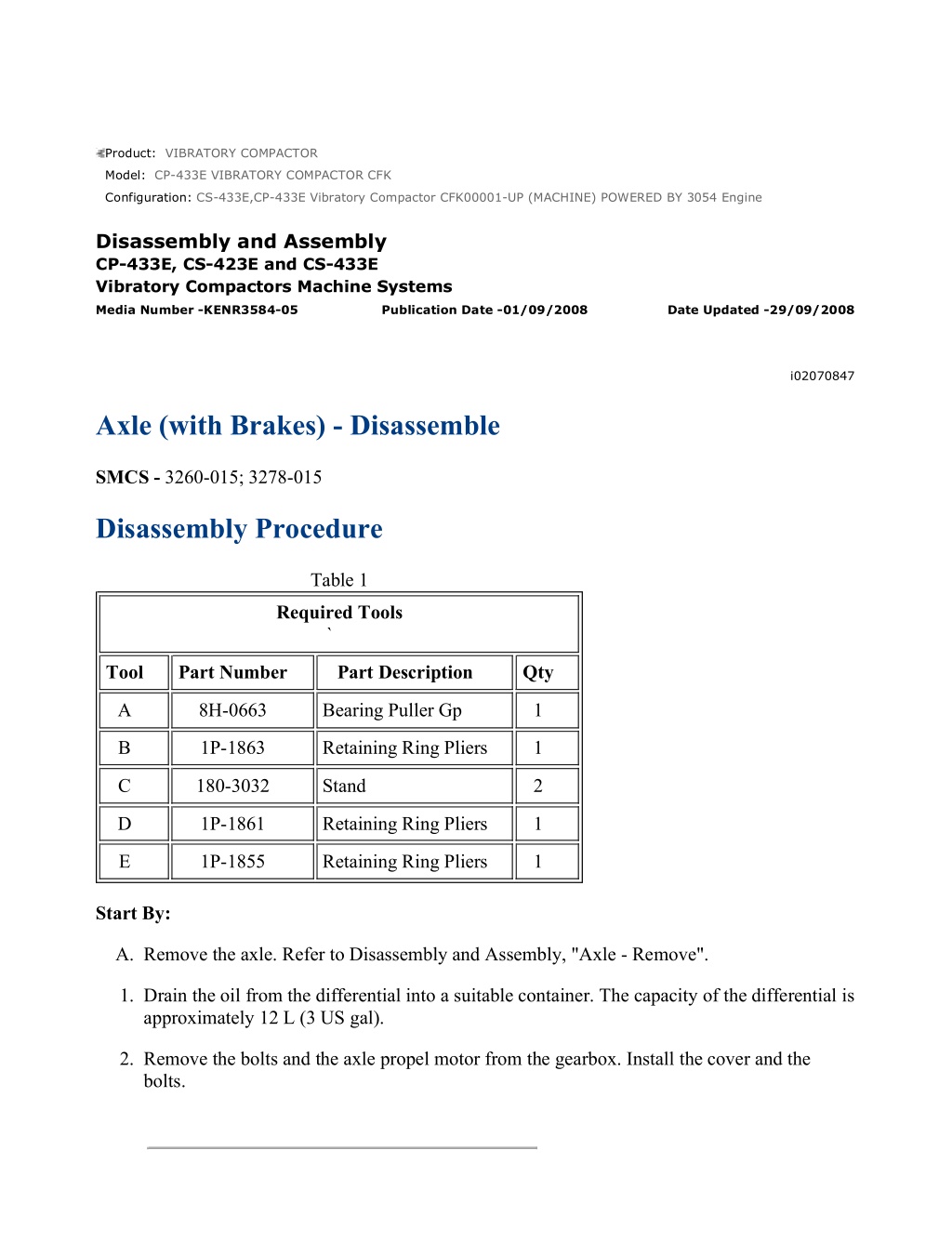
CS-433E,CP-433E Vibratory Compactor CFK00001-UP (MACHINE) POWERED B... 1/13 Product: VIBRATORY COMPACTOR Model: CP-433E VIBRATORY COMPACTOR CFK Configuration: CS-433E,CP-433E Vibratory Compactor CFK00001-UP (MACHINE) POWERED BY 3054 Engine Disassembly and Assembly CP-433E, CS-423E and CS-433E Vibratory Compactors Machine Systems Media Number -KENR3584-05 Publication Date -01/09/2008 Date Updated -29/09/2008 i02070847 Axle (with Brakes) - Disassemble SMCS - 3260-015; 3278-015 Disassembly Procedure Table 1 Required Tools ` Tool Part Number Part Description Qty A 8H-0663 Bearing Puller Gp 1 B 1P-1863 Retaining Ring Pliers 1 C 180-3032 Stand 2 D 1P-1861 Retaining Ring Pliers 1 E 1P-1855 Retaining Ring Pliers 1 Start By: A. Remove the axle. Refer to Disassembly and Assembly, "Axle - Remove". 1. Drain the oil from the differential into a suitable container. The capacity of the differential is approximately 12 L (3 US gal). 2. Remove the bolts and the axle propel motor from the gearbox. Install the cover and the bolts. https://127.0.0.1/sisweb/sisweb/techdoc/techdoc_print_page.jsp?returnurl=/sis... 2021/4/23
CS-433E,CP-433E Vibratory Compactor CFK00001-UP (MACHINE) POWERED B... 2/13 Illustration 1 g00847459 3. Drain the oil from the gearbox into a suitable container. The capacity of the gearbox is approximately 1.2 L (0.3 US gal). 4. Remove bolts (1) and cover (2) . Illustration 2 g00847460 5. Remove O-ring seal (3) from cover (2) . https://127.0.0.1/sisweb/sisweb/techdoc/techdoc_print_page.jsp?returnurl=/sis... 2021/4/23
CS-433E,CP-433E Vibratory Compactor CFK00001-UP (MACHINE) POWERED B... 3/13 Illustration 3 g00847461 6. Remove bolts (4) and cover (5) . Illustration 4 g00847462 7. Remove dowels (6) from cover (5) . Illustration 5 g00847463 8. Remove gear (6) and (7) . https://127.0.0.1/sisweb/sisweb/techdoc/techdoc_print_page.jsp?returnurl=/sis... 2021/4/23
https://www.ebooklibonline.com Hello dear friend! Thank you very much for reading. Enter the link into your browser. The full manual is available for immediate download. https://www.ebooklibonline.com
CS-433E,CP-433E Vibratory Compactor CFK00001-UP (MACHINE) POWERED B... 4/13 Illustration 6 g00847464 9. Use Tooling (A) and a suitable press to remove bearing (8) from gear (7) . Illustration 7 g00847465 10. Use Tooling (A) and a suitable press to remove bearing (9) from gear (7) . Illustration 8 g00847466 11. Use Tooling (A) and a suitable press to remove bearing (10) from gear (6) . https://127.0.0.1/sisweb/sisweb/techdoc/techdoc_print_page.jsp?returnurl=/sis... 2021/4/23
CS-433E,CP-433E Vibratory Compactor CFK00001-UP (MACHINE) POWERED B... 5/13 Illustration 9 g00847467 12. Use Tooling (B) to remove retaining ring (11). Use Tooling (A) and a suitable press to remove bearing (12) from gear (6) . Illustration 10 g00847468 13. Remove bolts (13) and remove cover (14) . https://127.0.0.1/sisweb/sisweb/techdoc/techdoc_print_page.jsp?returnurl=/sis... 2021/4/23
CS-433E,CP-433E Vibratory Compactor CFK00001-UP (MACHINE) POWERED B... 6/13 Illustration 11 g00847469 14. Drain the oil from the wheel hub into a suitable container. The capacity of the wheel hub is approximately 1.3 L (0.3 US gal). 15. Remove screws (15) and end cover (16) . Illustration 12 g00847471 16. Remove bolts (17), washers (18), planetary gears (19), and the 84 needle bearings. Illustration 13 g01061929 17. Remove O-ring seal (20) from ring gear (23) . 18. Remove shaft (21) . 19. Remove bolts (22) . https://127.0.0.1/sisweb/sisweb/techdoc/techdoc_print_page.jsp?returnurl=/sis... 2021/4/23
CS-433E,CP-433E Vibratory Compactor CFK00001-UP (MACHINE) POWERED B... 7/13 Illustration 14 g01065545 20. Install two bolts (22) to ring gear (23), as shown. Turn the bolts evenly in order to remove the ring gear. Discard bolts (22) . Illustration 15 g01065550 21. Use a suitable press and remove bushings (24) from ring gear (23) . Illustration 16 g01061619 https://127.0.0.1/sisweb/sisweb/techdoc/techdoc_print_page.jsp?returnurl=/sis... 2021/4/23
CS-433E,CP-433E Vibratory Compactor CFK00001-UP (MACHINE) POWERED B... 8/13 22. Remove bearing cone (28) and hub (25) . Illustration 17 g01066679 23. Remove lip seal (27) and bearing cups (28) from hub (25) . 24. Repeat Steps 14 through 23 in order to disassemble the other wheel hub. Illustration 18 g01061899 Note: During the removal of the housing, place a suitable jack under the other end of the axle. 25. Attach a suitable lifting device to the axle. Position the axle on Tooling (C), as shown. Remove bolts (30) and remove housing (29). The weight of housing (29) is approximately 41 kg (90 lb). https://127.0.0.1/sisweb/sisweb/techdoc/techdoc_print_page.jsp?returnurl=/sis... 2021/4/23
CS-433E,CP-433E Vibratory Compactor CFK00001-UP (MACHINE) POWERED B... 9/13 Illustration 19 g01061900 26. Remove O-ring seal (31) from housing (29) . Illustration 20 g01061901 27. Remove bearing cone (32) from housing (29) . Illustration 21 g01061903 28. Remove coupling (36) from shaft (35) . https://127.0.0.1/sisweb/sisweb/techdoc/techdoc_print_page.jsp?returnurl=/sis... 2021/4/23
CS-433E,CP-433E Vibratory Compactor CFK00001-UP (MACHINE) POWERED ... 10/13 29. Remove steel discs (34), friction discs (33), and shaft (35) from the axle. Illustration 22 g01061904 30. Attach a suitable lifting device to housing (37). Remove bolts (38) and remove housing (37). The weight of housing (37) is approximately 50 kg (110 lb). 31. Repeat Steps 24 through 30 in order to remove the other housing. 32. Remove gear assembly (39) . Illustration 23 g01061907 https://127.0.0.1/sisweb/sisweb/techdoc/techdoc_print_page.jsp?returnurl=/sis... 2021/4/23
CS-433E,CP-433E Vibratory Compactor CFK00001-UP (MACHINE) POWERED ... 11/13 Illustration 24 g01061909 Sudden release of spring force can cause injury. To prevent the possibility of injury, follow the procedure to relieve the spring pressure. 33. Remove O-ring seal (42) from housing (37) . 34. Put housing (37) in a suitable press. Apply pressure on spring washers (41). Use Tooling (D) to remove retaining ring (40) . 35. Release the pressure on spring washers (41) and remove the spring washers from housing (37) . Illustration 25 g01061911 https://127.0.0.1/sisweb/sisweb/techdoc/techdoc_print_page.jsp?returnurl=/sis... 2021/4/23
CS-433E,CP-433E Vibratory Compactor CFK00001-UP (MACHINE) POWERED ... 12/13 Illustration 26 g01061912 36. Use Tooling (E) to remove retaining rings (43). Remove bolts (45) and piston assemblies (44) . Illustration 27 g01061913 37. Remove O-ring seals (46) from piston assemblies (44) . Illustration 28 g01061915 https://127.0.0.1/sisweb/sisweb/techdoc/techdoc_print_page.jsp?returnurl=/sis... 2021/4/23
CS-433E,CP-433E Vibratory Compactor CFK00001-UP (MACHINE) POWERED ... 13/13 38. Remove bolt (47) and retainer (48) . Illustration 29 g01061917 39. Remove O-ring seals (50) from brake piston (49) . 40. Repeat Steps 33 through 39 in order to disassemble the other housing. https://127.0.0.1/sisweb/sisweb/techdoc/techdoc_print_page.jsp?returnurl=/sis... 2021/4/23
CS-433E,CP-433E Vibratory Compactor CFK00001-UP (MACHINE) POWERED B... 1/10 Product: VIBRATORY COMPACTOR Model: CP-433E VIBRATORY COMPACTOR CFK Configuration: CS-433E,CP-433E Vibratory Compactor CFK00001-UP (MACHINE) POWERED BY 3054 Engine Disassembly and Assembly CP-433E, CS-423E and CS-433E Vibratory Compactors Machine Systems Media Number -KENR3584-05 Publication Date -01/09/2008 Date Updated -29/09/2008 i02070613 Axle (without Brakes) - Assemble SMCS - 3260-016; 3278-016 Assembly Procedure Table 1 Required Tools Tool Part Number Part Description Qty B 1P-1859 Retaining Ring Pliers 1 C 1P-0510 Driver Gp 1 E 138-7573 Link Brackets 2 F 1U-8846 Gasket Sealant 1 G 155-0695 Thread Lock Compound 1 H 069-4707 Sealant 1 1. Inspect all parts and clean all parts. If any parts are worn or damaged, use new Caterpillar parts for replacement. 2. Inspect all seals. Damaged seals must be replaced. Use new Caterpillar seals for replacement. https://127.0.0.1/sisweb/sisweb/techdoc/techdoc_print_page.jsp?returnurl=/sis... 2021/4/23
CS-433E,CP-433E Vibratory Compactor CFK00001-UP (MACHINE) POWERED B... 2/10 Illustration 1 g01066510 3. Clean both mating surfaces of the differential and bevel gear and the axle housing. 4. Apply a continuous bead of Tooling (F) to the axle housing. 5. Install the differential and bevel gear (34) with Tooling (E) and a suitable lifting device. The weight of the differential and bevel gear is approximately 28 kg (62 lb). Remove Tooling (E) . Illustration 2 g01061635 https://127.0.0.1/sisweb/sisweb/techdoc/techdoc_print_page.jsp?returnurl=/sis... 2021/4/23
CS-433E,CP-433E Vibratory Compactor CFK00001-UP (MACHINE) POWERED B... 3/10 Illustration 3 g01066506 6. Install bolts (35). Tighten the bolts (35) to a torque of 169 N m (125 lb ft). 7. Install seal (33) into housing (32) with Tooling (C) and a suitable press. Install cover (32) on differential and bevel gear (34) . Illustration 4 g01061633 8. Install right shaft assembly (31) in the axle. Illustration 5 g01061632 9. Install left shaft assembly (30) in the axle. https://127.0.0.1/sisweb/sisweb/techdoc/techdoc_print_page.jsp?returnurl=/sis... 2021/4/23
CS-433E,CP-433E Vibratory Compactor CFK00001-UP (MACHINE) POWERED B... 4/10 Illustration 6 g01061629 10. Lower the temperature of the bearing cups (29) to a temperature of -51 C (-60 F). Install the bearing cups in hub (25) . 11. Install lip seal (28) in hub (25) . Illustration 7 g01061625 Illustration 8 g01061619 https://127.0.0.1/sisweb/sisweb/techdoc/techdoc_print_page.jsp?returnurl=/sis... 2021/4/23
CS-433E,CP-433E Vibratory Compactor CFK00001-UP (MACHINE) POWERED B... 5/10 12. Install bearing cone (27), hub (25), and bearing cone (26) . Illustration 9 g01064990 13. Use a suitable press and install bushings (24) in ring gear (23) . Illustration 10 g01064656 14. Install new bolts (22). Tighten the bolts (22) to a torque of 230 N m (170 lb ft). 15. Install shaft (21) . 16. Install O-ring seal (20) on ring gear (22) . https://127.0.0.1/sisweb/sisweb/techdoc/techdoc_print_page.jsp?returnurl=/sis... 2021/4/23
CS-433E,CP-433E Vibratory Compactor CFK00001-UP (MACHINE) POWERED B... 6/10 Illustration 11 g00847471 17. Install the 84 needle bearings, gears (19), washers (18), and bolts (17) . Illustration 12 g00847469 18. Install end cover (16) and screws (15) . 19. Fill the wheel hub with oil. The capacity of the wheel hub is approximately 1.3 L (0.3 US gal). Refer to Operation and Maintenance Manual for the correct procedure. 20. Repeat Steps 10 through 19 in order to assemble the other wheel hub. https://127.0.0.1/sisweb/sisweb/techdoc/techdoc_print_page.jsp?returnurl=/sis... 2021/4/23
CS-433E,CP-433E Vibratory Compactor CFK00001-UP (MACHINE) POWERED B... 7/10 Illustration 13 g00847468 21. Apply Tooling (H) to the axle housing. Install cover (14). Apply Tooling (G) to bolts (13) and install the bolts. Tighten the bolts to a torque of 120 N m (89 lb ft). Illustration 14 g00847467 22. Use a suitable press and install bearing (12) on gear (6). Use Tooling (B) to install retaining ring (11) . Illustration 15 g00847466 https://127.0.0.1/sisweb/sisweb/techdoc/techdoc_print_page.jsp?returnurl=/sis... 2021/4/23
CS-433E,CP-433E Vibratory Compactor CFK00001-UP (MACHINE) POWERED B... 8/10 23. Use a suitable press and install bearing (10) on gear (6) . Illustration 16 g00847465 24. Use a suitable press and install bearing (9) on gear (7) . Illustration 17 g00847464 25. Use a suitable press and install bearing (8) on gear (7) . https://127.0.0.1/sisweb/sisweb/techdoc/techdoc_print_page.jsp?returnurl=/sis... 2021/4/23
CS-433E,CP-433E Vibratory Compactor CFK00001-UP (MACHINE) POWERED B... 9/10 Illustration 18 g00847463 26. Install gear (7) and gear (6) . Illustration 19 g00847462 27. Install dowels (6) on cover (5). Apply Tooling (H) on cover (5) . Illustration 20 g00847461 28. Install cover (5) and bolts (4). Tighten the bolts to a torque of 60 N m (44 lb ft). https://127.0.0.1/sisweb/sisweb/techdoc/techdoc_print_page.jsp?returnurl=/sis... 2021/4/23
CS-433E,CP-433E Vibratory Compactor CFK00001-UP (MACHINE) POWERED ... 10/10 Illustration 21 g00847460 29. Install O-ring seal (3) on cover (2) . Illustration 22 g00847459 30. Install cover (2) and bolts (1). Tighten the bolts to a torque of 60 N m (44 lb ft). 31. Remove the bolts and the cover from the gearbox. Install the propel motor and the bolts on the gearbox. 32. Fill the gearbox with oil. The capacity of the gearbox is 1.2 L (0.3 US gal). 33. Fill the differential with oil. The capacity of the differential is 9 L (2.4 US gal). End By: Install the axle. Refer to Disassembly and Assembly, "Axle - Install". https://127.0.0.1/sisweb/sisweb/techdoc/techdoc_print_page.jsp?returnurl=/sis... 2021/4/23
CS-433E,CP-433E Vibratory Compactor CFK00001-UP (MACHINE) POWERED B... 1/13 Product: VIBRATORY COMPACTOR Model: CP-433E VIBRATORY COMPACTOR CFK Configuration: CS-433E,CP-433E Vibratory Compactor CFK00001-UP (MACHINE) POWERED BY 3054 Engine Disassembly and Assembly CP-433E, CS-423E and CS-433E Vibratory Compactors Machine Systems Media Number -KENR3584-05 Publication Date -01/09/2008 Date Updated -29/09/2008 i02162119 Axle (with Brakes) - Assemble SMCS - 3260-016; 3278-016 Assembly Procedure Table 1 Required Tools Tool Part Number Part Description Qty B 1P-1863 Retaining Ring Pliers 1 C 180-3032 Stand 2 D 1P-1861 Retaining Ring Pliers 1 E 1P-1855 Retaining Ring Pliers 1 F 069-4707 Sealant 1 G 155-0695 Thread Lock Compound 1 1. Inspect all parts and clean all parts. If any parts are worn or damaged, use new Caterpillar parts for replacement. 2. Inspect all seals. Damaged seals must be replaced. Use new Caterpillar seals for replacement. https://127.0.0.1/sisweb/sisweb/techdoc/techdoc_print_page.jsp?returnurl=/sis... 2021/4/23
CS-433E,CP-433E Vibratory Compactor CFK00001-UP (MACHINE) POWERED B... 2/13 Illustration 1 g01061917 3. Install O-ring seals (50) on brake piston (49) . Illustration 2 g01061915 4. Install retainer (48) and bolt (47) . Illustration 3 g01061913 5. Install O-ring seals (46) on piston assemblies (44) . https://127.0.0.1/sisweb/sisweb/techdoc/techdoc_print_page.jsp?returnurl=/sis... 2021/4/23
CS-433E,CP-433E Vibratory Compactor CFK00001-UP (MACHINE) POWERED B... 3/13 Illustration 4 g01061911 Illustration 5 g01061912 6. Install piston assemblies (44). Use Tooling (E) to install retaining rings (43) . 7. Install bolts (45). Tighten the bolts (45) to a torque of 10 N m (8 lb ft). Illustration 6 g01061909 https://127.0.0.1/sisweb/sisweb/techdoc/techdoc_print_page.jsp?returnurl=/sis... 2021/4/23
CS-433E,CP-433E Vibratory Compactor CFK00001-UP (MACHINE) POWERED B... 4/13 Illustration 7 g01061907 Sudden release of spring force can cause injury. To prevent the possibility of injury, follow the procedure to relieve the spring pressure. 8. Put housing (37) in a suitable press. Install spring washers (41). Apply pressure on the spring washers. Use Tooling (D) to install retaining ring (40). Release the pressure on the spring washers. 9. Install O-ring seal (42) on housing (37) . 10. Repeat Steps 3 through 9 in order to assemble the other housing. Illustration 8 g01061904 https://127.0.0.1/sisweb/sisweb/techdoc/techdoc_print_page.jsp?returnurl=/sis... 2021/4/23
CS-433E,CP-433E Vibratory Compactor CFK00001-UP (MACHINE) POWERED B... 5/13 11. Install gear assembly (39) . 12. Attach a suitable lifting device to housing (37). Install housing (37) and bolts (38). The weight of housing (37) is approximately 50 kg (110 lb). Tighten bolts (38) to a torque of 102 N m (75 lb ft). 13. Repeat Step 12 in order to install the other housing. Illustration 9 g01061903 14. Install shaft (35), friction discs (33), and steel discs (34) . 15. Install coupling (36) on shaft (35) . Illustration 10 g01061901 16. Install bearing cone (32) on housing (29) . https://127.0.0.1/sisweb/sisweb/techdoc/techdoc_print_page.jsp?returnurl=/sis... 2021/4/23
Suggest: If the above button click is invalid. Please download this document first, and then click the above link to download the complete manual. Thank you so much for reading
CS-433E,CP-433E Vibratory Compactor CFK00001-UP (MACHINE) POWERED B... 6/13 Illustration 11 g01061900 17. Install O-ring seal (31) on housing (29) . Illustration 12 g01061899 18. Attach a suitable lifting device to housing (29). Install axle housing (29) and bolts (30). Tighten the bolts to a torque of 170 N m (125 lb ft). 19. Repeat Steps 14 through 18 in order to install the other housing. https://127.0.0.1/sisweb/sisweb/techdoc/techdoc_print_page.jsp?returnurl=/sis... 2021/4/23
https://www.ebooklibonline.com Hello dear friend! Thank you very much for reading. Enter the link into your browser. The full manual is available for immediate download. https://www.ebooklibonline.com

