Analysis of Low-Frequency Response in BJT and FET Amplifiers
This analysis delves into the low-frequency response of BJT and FET amplifiers, examining the impact of various components such as resistors and capacitors on the cutoff frequencies. Detailed examples illustrate the calculation process for determining these frequencies based on specific parameters. Additionally, the influence of bypass capacitors on the lower cutoff frequency of the amplifier is explored. The content provides a comprehensive understanding of how different elements affect the performance of amplifiers in low-frequency scenarios.

Download Presentation

Please find below an Image/Link to download the presentation.
The content on the website is provided AS IS for your information and personal use only. It may not be sold, licensed, or shared on other websites without obtaining consent from the author. Download presentation by click this link. If you encounter any issues during the download, it is possible that the publisher has removed the file from their server.
E N D
Presentation Transcript
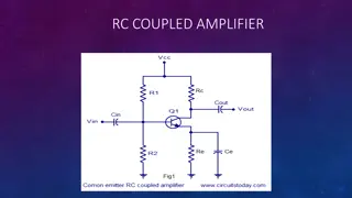
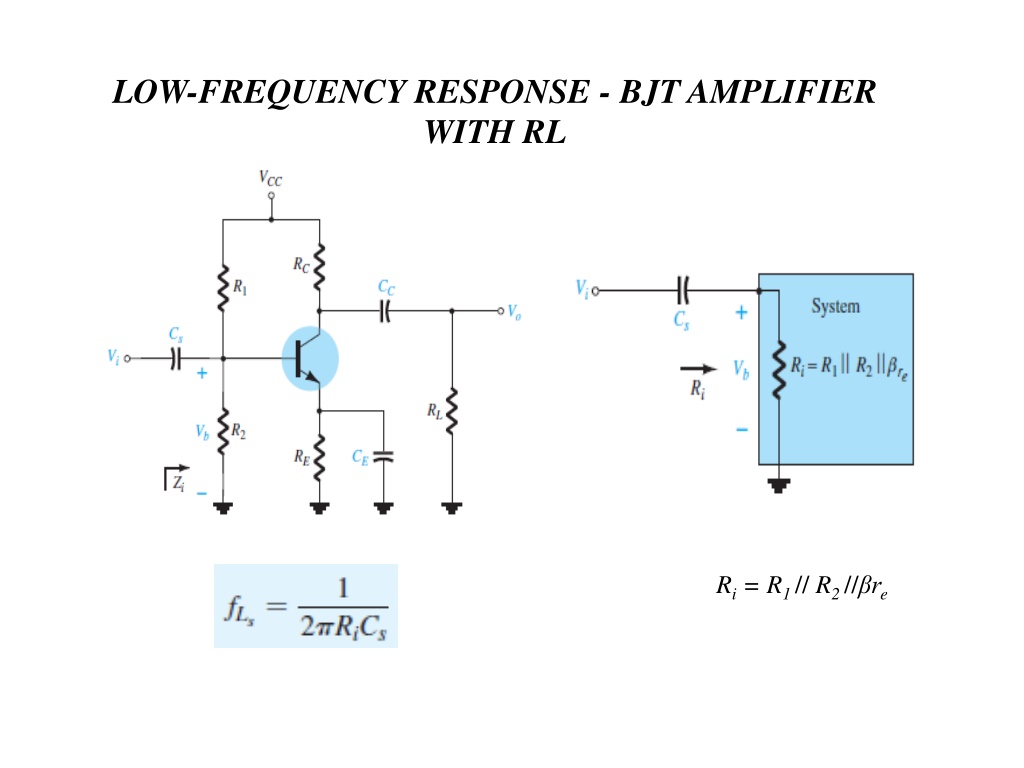
LOW-FREQUENCY RESPONSE - BJT AMPLIFIER WITH RL Ri = R1 // R2 // re
Example (1): Determine the cutoff frequencies for the network of fig.1. using the following parameters : CS = 10 f , CE = 20 f , CC = 1 f , R1 = 40k , R2= 10k , RE= 2k , RC = 4k , RL= 2.2k , = 100 , VCC = 20v , ro= ? Solution: The dc base voltage is determined by ?2??? ?1+ ?2 10? 20? 10? + 40? =200? ??= = = 4? 50 ??=?? =4? 0.7? 2? =3.3? 2? = 1.65?? ?? 26?? 1.65?? 15.76 ??= ???= 100 15.76 = 1576 = 1.576? The Midband Gain of the system is determined by: ??=?? = ?? ?? = (4? ) (2.2? ) 15.76 = 90 ?? ?? For Cs ??= ?1?2???= 40? 10? 1.576? 1.32? 1 2????? 6.28 1.32? 10?? 1 ???= = 12.06 H?
For Cc 1 ???= 2? ??+???? , ??= ?? ?? ?? 1 = 25.68 H? 6.28 4? + 2.2? 1?? For CE ??= ?? ?1 ?2 ? + ?? 40? 10? 100 8? 100+ 15.76 = 2? 80 + 15.76 = 2? 95.76 = 91.38 = 2? + 15.76 = 2? 1 1 ???= = 87.13 H? 2????? 6.28 91.38 20?? Since fLE>> fLCor fLS the bypass capacitor CE is determining the lower cutoff frequ-ency of the amplifier.
Example (2): Determine the cutoff frequencies for the network of fig.2. using the following parameters : CS = 10 f , CE = 20 f , CC = 1 f , RS = 1k , R1 = 40k , R2 = 10k , RE = 2k , RC = 4k , RL = 2.2k , = 100 , VCC = 20v , ro = ? Solution: The dc base voltage is determined by ?2??? ?1+ ?2 10? 20? 10? + 40? =200? ??= = = 4? 50 ??=?? =4? 0.7? 2? =3.3? 2? = 1.65?? ?? 26?? 1.65?? 15.76 ??= ???= 100 15.76 = 1576 = 1.576? The Midband Gain of the system is determined by: ??=?? = ?? ?? = (4? ) (2.2? ) 15.76 = 90 ?? ?? ??= ?1?2???= 40? 10? 1.576? 1.32? ???? ??+ ?? ???=?? =?? ?? ?? ?? ?? ?? 1.32? 1.32? + 1? = 0.569 ??= = 90 0.569 = 51.21 = = ?? ?? ??+ ??
For Cs fLS=12 (Rs+Ri)Cs=16.281k +1.32k 10 f 6.86 Hz For Cc fLc=12 Ro+RLCc , Ro=Rc ro Rc=16.284k +2.2k 1 f 25.68 Hz For CE R's=RsR1R2=1k 40k 10k 0.889k Re=RE R's +re =2k 0.889k 100+15.76 =2k 8.89 +15.76 =2k 24.65 24.35 fLE=12 ReCE=16.2824.35 20 f 327 Hz
Example (3): Determine the cutoff frequencies for the network of fig.3. using the following parameters : CS = 2 f , CG = 0.01 f , CC = 0.5 f , RSig = 10k , RG = 1M , RD = 4.7k , RS = 1k , RL = 2.2k , IDSS = 8mA , Vd = -4v , rd = , VDD =20v,VGSQ = -2v Solution: The dc base voltage is determined by: ??0=2???? =2 8?? = 4?? ?? 4? ??= ??0 1 ???? ?? ??= 4?? 1 2? = 2?? 4? For CG 1 1 ???= = 2?(????+ ??)?? 15.8 H? For Cc 1 2?(??+ ??)?? 6.28 10? + 1? 0.01?? 1 ???= = 46.13 H? 6.28 4.7? + 2.2? 0.5??
For CS 1 1 ???= ?? = 1? 2??= 1? 0.5? = 333.33 1 6.28 333.33 2?? ?? 1 ???= = = 238.73 H? 2?????? Because fLS is the largest of the three cutoff frequencies, it defines the low-cutoff frequency for the network of Fig.3. The Midband Gain of the system is determined by: ?????=?? ?? = 2?? 1.4? 3 = ??(???? = ( 2??)(4.7? 2.2? )
Example (4): Determine the high-cutoff frequencies for the network of fig.4. using the following parameters : CS = 10 f , CE = 20 f , CC = 1 f , RS = 1k , R1 = 40k , R2= 10k , RE= 2k , RC= 4k , RL= 2.2k , = 100 , VCC = 20v , ro= , Cbe = 36pf, Cbc = 4pf, Cce = 1pf, CWi = 6pf, CWo = 8pf? Solution: The dc base voltage is determined by ?2??? ?1+ ?2 10? 20? 10? + 40? =200? ??= = = 4? 50 ??=?? =4? 0.7? 2? =3.3? 2? = 1.65?? ?? 26?? 1.65?? 15.76 ??= ???= 100 15.76 = 1576 = 1.576? The Midband Gain of the system is determined by: ??=?? ?? ?? ?? ?= ???1?2???= 1? 40? 10? 576? 0.57? With Ci = Cwi + Cbe + CMi , CMi = ( 1- Av) Cbc Ci = Cwi + Cbe + ( 1- Av) Cbc = 6pf + 36pf + [ 1 - (-90)] 4pf = 406pf = ?? ?? = (4? ) (2.2? ) 15.76 = 90
1 1 ???= = = 687.73 ?H? 2??? ??? ?? ?= ????= 4? 2.2? = 1.419? With Co = Cwo + Cce + CMo , CMo = ( 1- 1/Av) Cbc Co = Cwo + Cce + ( 1- 1/Av) Cbc = 8pf + 1pf + [ 1- 1/(-90)] 4pf = 13.04pf 1 2??? ??? 6.28 0.57? 406?? 1 ???= = = 8.6 ?H? 6.28 1.419? 13.04??
Example (5): Determine the high-cutoff frequencies for the network of fig.5. using the following parameters : CS = 2 f , CG = 0.01 f , CC = 0.5 f , RSig = 10k , RG = 1M , RD = 4.7k , RS = 1k , RL = 2.2k , IDSS = 8mA , Vd = -4v , rd = , VDD =20v,VGSQ = -2v, Cgd = 2pf, Cgs = 4pf, Cds = 0.5pf, CWi = 5pf, CWo = 6pf ? Solution: The dc base voltage is determined by: ??0=2???? =2 8?? = 4?? ?? 4? ??= ??0 1 ???? ?? ??= 4?? 1 2? = 2?? 4? The Midband Gain of the system is determined by ?????=?? = ??(???? = ( 2??)(4.7? 2.2? ) ?? = 2?? 1.4? 3 ?? ?= ??????= 10? 1? = 9.9? With Ci = Cwi + Cgs + CMi , CMi = ( 1- Av) Cgd Ci = Cwi + Cgs + ( 1- Av) Cgd = 5pf + 4pf + ( 1+ 3) 2pf = 9pf + 8pf = 17pf
1 1 ???= = = 945.67 ?H? 2??? ??? ?? ?= ????= 4.7? 2.2? 1.5? With Co = Cwo + Cds + CMo , CMo = ( 1- 1/Av) Cgd Co = Cwo + Cds + ( 1- 1/Av) Cgd = 6pf + 0.5pf + [ 1 1/ (-3) ] 2pf = 9.17pf 1 2??? ??? 6.28 1.5? 9.17?? 6.28 9.9? 17?? 1 ???= = = 11.57 ?H?


: Determine the cutoff frequencies for the")

: Determine the cutoff frequencies for the")

: Determine the cutoff frequencies for the")

: Determine the high-cutoff frequencies for the")

: Determine the high-cutoff frequencies for the")