Understanding Frequency Hopping Spread Spectrum Systems
Frequency Hopping Spread Spectrum (FH-SSS) is a technique where the carrier frequency changes randomly using a Pseudo-Noise (PN) code. It is widely used in mobile civilian and military communications for secure and efficient data transmission. FH-SSS systems are classified as Fast or Slow based on the hop rate in relation to the data rate, with Fast FH-SSS using multiple carrier frequencies per data bit transmission. The modulation of carriers by data and address codes plays a crucial role in FH systems. Synchronization between the transmitter and receiver PN generators is essential for successful operation. Explore the intricacies and applications of FH-SSS for robust communication.
Download Presentation

Please find below an Image/Link to download the presentation.
The content on the website is provided AS IS for your information and personal use only. It may not be sold, licensed, or shared on other websites without obtaining consent from the author. Download presentation by click this link. If you encounter any issues during the download, it is possible that the publisher has removed the file from their server.
E N D
Presentation Transcript
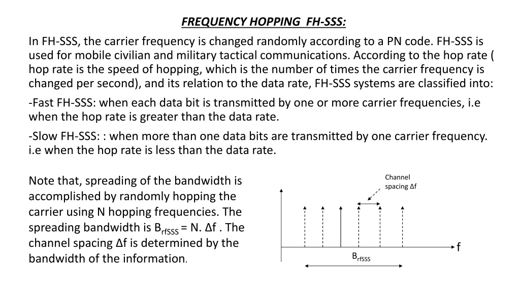
FREQUENCY HOPPING FH-SSS: In FH-SSS, the carrier frequency is changed randomly according to a PN code. FH-SSS is used for mobile civilian and military tactical communications. According to the hop rate ( hop rate is the speed of hopping, which is the number of times the carrier frequency is changed per second), and its relation to the data rate, FH-SSS systems are classified into: -Fast FH-SSS: when each data bit is transmitted by one or more carrier frequencies, i.e when the hop rate is greater than the data rate. -Slow FH-SSS: : when more than one data bits are transmitted by one carrier frequency. i.e when the hop rate is less than the data rate. Channel spacing f Note that, spreading of the bandwidth is accomplished by randomly hopping the carrier using N hopping frequencies. The spreading bandwidth is BrfSSS= N. f . The channel spacing f is determined by the bandwidth of the information. f BrfSSS
According to the modulation of carrier by data and address code, the following FH systems are given: 1-FH-SSS with conventional modulation: Here, the frequency hopper is controlled by a PN code, while the data signal (may be analog or digital) modulates the hopping carrier. fo= m . fr, where m is the random address set by the k-bit PN code generator 2k> m > 0 fr data K bit fo Analog information At the Tx side, the PN code generator is driven by a clock that determines the hop rate. The k-bit parallel outputs of the PN generator are used to control the instantaneous carrier frequency fo.
The reference frequency fris obtained from a high stable crystal oscillator. This fois then used in any conventional modulator (may be analog or digital) to produce the FH signal. information flocal K bit At the Rx side, there is an identical PN generator controlling the frequency synthesizer. The local frequency flocalhops synchronously with that at the Tx with a constant IF frequency between them, i.e:
fIF= fo- flocal(note: both foand flocalhops randomly but the difference between them is kept constant as the IF frequency) . Note: Suggested Seminar (report)on Frequency Synthesizers(types, operations,..etc): 2-FH system with single channel data modulation: First, the carrier is modulated by a digital information signal and then the modulated carrier hops according to the PN code by a mixer & frequency synthesizer ( up conversion to fo), i.e, the data is first modulated then hopped. mixer fo data fc
Hopping pattern hopping clock 1 2 3 4 5 6 f2 f4 f3 f6 f1 f5 f f1 f2 f3 f4 f5 f6 Hopping pattern f2 f4 f3 f6 f1 f5 Th 2Th 3Th 4Th 5Th 6Th f
If synchronization is achieved between the Tx and Rx PN generators, then the mixer output set at a certain fIF= fo-flocalis applied to the IF amplifier with a bandwidth equals the bandwidth of the PSK signal. data mixer
