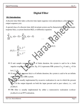
Understanding Active Filters: Low Pass and High Pass Filter Designs
Explore the world of active filters, specifically 1st and 2nd order low pass and high pass filters. Learn about their circuit designs, advantages over passive filters, gain equations, frequency responses, and practical steps for designing custom low pass filters. Dive into the realm of frequency-selective circuits for communication and signal processing applications.

Download Presentation

Please find below an Image/Link to download the presentation.
The content on the website is provided AS IS for your information and personal use only. It may not be sold, licensed, or shared on other websites without obtaining consent from the author. Download presentation by click this link. If you encounter any issues during the download, it is possible that the publisher has removed the file from their server.
E N D
Presentation Transcript
Active filters 1st & 2nd order low pass and high pass filter
*Active filters and oscillators An electric filter is often a frequency selective circuit that passes a specified band of frequencies and block or attenuates signals of frequencies outside this band. Classified of filters 1. Analog or digital 2. Passive or active 3. Audio and radio frequency
Active filters As their name implies, Active Filters contain active components such as operational amplifiers, transistors or FET s within their circuit design. They draw their power from an external power source and use it to boost or amplify the output signal. These are generally used in communication and signal processing i.e. radio, television etc. Advantage of Active filters over Passive filters 1. 2. No loading problem (because of high i/p and low o/p resistance of op-amp) 3. Active filters are cheaper than passive filters Gain and frequency adjustment flexibility
First order low pass filter Fig.1 circuit diagram Fig.2 Frequency response Note : The op-Amp is used in the non- inverting configuration ; hence it does not load down the RC Network.
Gain of a first-order low pass filter Where: AF= the pass band gain of the filter, (1 + R2/R1) = the frequency of the input signal in Hertz, (Hz) c = the cut-off frequency in Hertz, (Hz) Thus, the operation of a low pass active filter can be verified from the frequency gain equation above as: 1. At very low frequencies, < c 2. At the cut-off frequency, = c 3. At very high frequencies, > c
Designing Low pass filter 1. Choose a value of high cut off Frequency c 2. Select a value of C less than or equal to 1 F. Mylar or tantalum capacitor are recommended for better performance. 3. Calculate R= 1/(2 cC) 4. Select R1 and R2 AF= the pass band gain of the filter, (1 + R2/R1)
Second Order Low pass Filter Fig 2. blue line show frequency response of 2nd order low pass filter Fig 1. circuit diagram
Filter design for 2nd order low pass filter 1. Choose a value of high cut off Frequency c 2. To simplify the design set R2 = R1 = R and C1= C2= C then choose C less than or equal to 1 F 3. Calculate R= 1/(2 cC) 4. AF= the pass band gain of the filter, (1 + Ra/Rb) = 1.589
First order HIGH PASS FILTER Fig circuit diagram Fig . Frequency response
Gain of a first-order Active pass filter Where: AF= the pass band gain of the filter, (1 + R2/R1) = the frequency of the input signal in Hertz, (Hz) c = the cut-off frequency in Hertz, (Hz) Thus, the operation of a low pass active filter can be verified from the frequency gain equation above as: 1. At very low frequencies, < c 2. At the cut-off frequency, = c 3. At very high frequencies, > c
2nd order high pass filter Fig. circuit diagram fig 2. Red line show the frequency response of 2nd order
Keep Learning Dr. Mona Bhatnagar