Amplifier Coupling Techniques and Applications
Amplifiers utilize various coupling techniques such as resistance-capacitance (RC), inductance (LC), transformer, and direct coupling to connect different stages. Each coupling method has its advantages and applications, such as impedance matching, power transfer, and amplification of radio frequency signals. Multistage amplifiers often employ RC, transformer, or direct coupling between stages to ensure signal continuity and proper functioning.

Download Presentation

Please find below an Image/Link to download the presentation.
The content on the website is provided AS IS for your information and personal use only. It may not be sold, licensed, or shared on other websites without obtaining consent from the author. Download presentation by click this link. If you encounter any issues during the download, it is possible that the publisher has removed the file from their server.
E N D
Presentation Transcript
TYPES OF COUPLING IN AMPLIFIER The types of coupling used in amplifiers 1. Resistance capacitance (RC) coupling. 2. Inductance (LC) coupling. 3. Transformer coupling (TC) 4. Direct coupling (D.C.) Visit for more Learning Resources Visit for more Learning Resources
Two stage transformer coupled amplifier.
Advantages: Transformer coupling is mostly employed for impedance matching It is used as final stage. It is used to transfer power to the low impedance lad such as loudspeaker. For amplification of radio frequency (RF) signal. In power amplifiers.
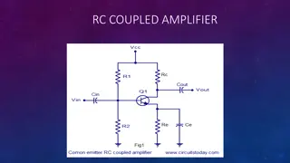
Operation of Single stage CE amplifier The circuit diagram of a voltage amplifier using single transistor in CE configuration is shown in figure. It is also known as a small-signal single-stage CE amplifier or RC coupled CE amplifier. It is also known as a voltage amplifier. The potential divider biasing is provided by resistors R1, R2 and RE. It provides good stabilization of the operating point. The capacitors CC1 and CC2 are called the coupling capacitors used to block the AC voltage signals at the input and the output sides. The capacitor CE works as a bypass capacitor. It bypasses all the AC currents from the emitter to the ground and avoids the negative current feedback. It increases the output AC voltage. The resistance RL represents the resistance of whatever is connected at the output. It may be load resistance or input resistance of the next stage
Types of Coupling in Multistage In multistage amplifiers, the output signal of preceding stage is to be connected to the input of next stage. Coupling techniques: 1. R-C coupling 2. Transformer Coupling 3. Direct Coupling
Advantages of RC coupled Amplifier 1. Wide frequency response 2. It is most convenient coupling 3. It is inexpensive way of coupling distortion in output is low 4. It is high fidelity amplifier 5. No core distortion
Application 1. In Public Address amplifier system 2. Tape Recorder 3. TV, VCR and CD player 4. Stereo amplifiers 5. RC coupled amplifiers are basically voltage amplifiers
Advantages 1. Impedance matching between the stages is possible 2. Higher voltage gain than RC coupled amplifiers 3. DC biasing of individual stages will remain unchanged even after cascading. Disadvantages 1. Coupling transformer is expensive and bulky 2. Frequency response is not perfectly flat 3. There is possibility of core saturation 4. Low frequency due to losses in transformer
Applications 1. For Impedance matching 2. For amplification of radio frequency (RF) signal 3. In power amplifiers 4. For transferring power to low impedance load and such as a loude speaker
Advantages 1. Due to absence of coupling capacitor, the gain does not reduce on the lower frequency side 2. Wide frequency response 3. This amplifier can amplify even the DC signal 4. Reduced cost and complexity due to absence of coupling capacitor Disadvantages 1. DC biasing conditions of the individual stages do not remain same after cascading 2. Poor frequency response at higher frequencies 3. Output waveform has DC shift 4. Poor temperature stability
Application 1. In operation Amplifiers (OP-AMP) 2. In analog computation 3. In linear Power supplies For more detail contact us For more detail contact us