Understanding Digital Meters in Electronics
Digital meters are essential instruments in electronics for accurate measurement of signals and frequencies. They offer advantages like high accuracy, resolution, and portability compared to traditional analog instruments. Learn about the principles, functionality, and components of digital meters, including digital frequency meters, amplifiers, Schmitt triggers, start-stop gates, counters, and displays. Explore how digital meters work and their significance in modern electronic systems.

Download Presentation

Please find below an Image/Link to download the presentation.
The content on the website is provided AS IS for your information and personal use only. It may not be sold, licensed, or shared on other websites without obtaining consent from the author. Download presentation by click this link. If you encounter any issues during the download, it is possible that the publisher has removed the file from their server.
E N D
Presentation Transcript
CHAPTER-3 DIGITAL METERS (20 MARKS) Mrs V.S.KharoteChavan,E&Tc,PC poly 1
Sr. No. Parameter Analog instrument Digital instrument 1 Principle The instrument that displays analog signals is displays digital signals is called as an analog instrument. Low Low draws more power Cheap Portable Considerable Observational error PMMC instrument, analog ammeter, analog voltmeter. The instrument that called as an digital instrument. High High draws less power costly Less Free from Observational error DMM, DVM 2 3 4 5 6 7 Accuracy Resolution Power Cost Portability Observationa l error examples 8 Mrs V.S.KharoteChavan,E&Tc,PC poly 2
digital frequency meter. Mrs V.S.KharoteChavan,E&Tc,PC poly 3
Digital frequency meter: Frequency is defined as number of cycles per unit time interval. The signal whose frequency is to be measured is used as an event. The unknown frequency is first converted to train of pulses. One pulse represents one cycle of unknown signal. These pulses are directly proportional to the frequency to be measured. Mrs V.S.KharoteChavan,E&Tc,PC poly 4
Amplifier: The signal whose frequency is to be measured is first amplified. The output of amplifier is applied to the Schmitt trigger. Schmitt trigger: The Schmitt trigger converts the signal into square wave having fast rise and fall times. The square wave is then differentiated and clipped. Each pulse is proportional to each cycle of unknown signal. Mrs V.S.KharoteChavan,E&Tc,PC poly 5
Start- Stop gate: The output from Schmitt trigger is applied to start and stop gate. These pulses are applied to the switch. This switch is controlled by a signal having definite time interval. The main gate switch is closed for known time interval. When the gate is open, input pulses are allowed to pass through it. A counter will now start to count these pulses. When the gate is closed, input pulses are not allowed to pass through the gate. The counter will now stop counting. Mrs V.S.KharoteChavan,E&Tc,PC poly 6
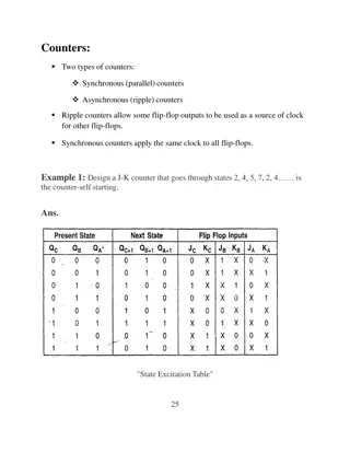
Counter and display: The number of pulses during the period gate is open are counted by the counter. If this interval between start andstop condition is known, frequency of unknown signal is measured. F= N/t Where, F= Unknown frequency N= Number of counts displayed by the counter. t= Time interval between start and stop condition of the gate. the Mrs V.S.KharoteChavan,E&Tc,PC poly 7
DIGITAL MULTIMETER BLOCK DIAGRAM Mrs V.S.KharoteChavan,E&Tc,PC poly 8
An unknown current to be measured is applied to one of the input terminals of op-amp. Let this input is. Since an input impedance of op-amp is very high; very small current can pass through it. This current passing into the op-amp can be neglected. Mrs V.S.KharoteChavan,E&Tc,PC poly 9
This feedback current is allowed to pass through one of the known resistances. This current will cause a voltage drop across the resistance. This voltage is applied to analog to digital converter and finally digital display is obtained. Thus output displayed on the digital display is directly proportional to unknown current. Mrs V.S.KharoteChavan,E&Tc,PC poly 10
In order to measure an unknown resistance; a constant current source is used. The current from this constant current source is allowed to pass through unknown resistance. Thus the proportional voltage is obtained. The output display is directly proportional to unknown resistance. Mrs V.S.KharoteChavan,E&Tc,PC poly 11
To measure the ac voltage; a rectifier and filter is used. This rectifier converts ac signal into dc signal. Now this dc signal is applied to A to D converter and to the digital display. The BCD output can be obtained from A to D converter. Similarly the output from digital multimeter can be used to interface with other equipments. Mrs V.S.KharoteChavan,E&Tc,PC poly 12
Specifications of DMM are as follows: D.C. Voltage: Voltage range from + 20 V to + 1000V Accuracy about + 0.03% Resolution is about 10 V AC Voltage: Voltage range from 200mV to 750 V Accuracy is frequency dependent. Resolution: 10 V Resistance: Resistance range from 200 to 20M accuracy: + 0.1% of reading Mrs V.S.KharoteChavan,E&Tc,PC poly 13
D.C. Current: Current range from + 200 A to 2 A. Accuracy + 0.3% of reading Resolution + 0.01 A A.C. Current: Range from 200 A to 2A Accuracy depends on frequency. Mrs V.S.KharoteChavan,E&Tc,PC poly 14
Here high stabilized amplifier is used to provide the amplification. The one terminal of stabilized amplifier is connected to the attenuator network which consists of five resistors. The other terminal is connected with feedback path. Capacitor is used to block d.c entering into stabilized non linearity problem created by diodes. Also the variation in impedance meter is compensated by negative feedback. The average reading is obtained by filtering the signal coming gives from the rectifier. Thus for meter movement gives response to average value. Mrs V.S.KharoteChavan,E&Tc,PC poly 16
Depending appropriate switches can be selected. The lower channel gives direct voltage at detector (generally calibrated in terms of Q) which can be then converted to digital signals and then displayed on digital panel meter. Along with basic circuit of measurement, the digital LCR-Q meter also incorporates auto zeroing, auto ranging and other facilities like indication of Low/ High battery and auto power off circuitry. on measurements, the Mrs V.S.KharoteChavan,E&Tc,PC poly 18