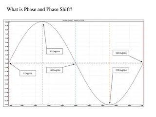
Understanding Lead and Phase-Lead Compensators

Lead or Phase-Lead Compensator Using Root Locus
A first-order lead compensator can be designed using the root locus. A lead compensator
in root locus form is given by
where the magnitude of z is less than the magnitude of p
.
A phase-lead compensator
tends to shift the root locus toward the left half plane. This results in an improvement in
the system's stability and an increase in the response speed.
When a lead compensator is added to a system, the value of this intersection will be a
larger negative number than it was before. The net number of zeros and poles will be the
same (one zero and one pole are added), but the added pole is a larger negative number
than the added zero. Thus, the result of a lead compensator is that the asymptotes'
intersection is moved further into the left half plane, and the entire root locus will be
shifted to the left. This can increase the region of stability as well as the response speed.
In Matlab a phase lead compensator in root locus form is implemented by using the
transfer function in the form
numlead=kc*[1 z];
denlead=[1 p];
and using the
conv()
function to implement it with the numerator and denominator
of the plant
newnum=conv(num,numlead);
newden=conv(den,denlead);
Lead or Phase-Lead Compensator Using Root Locus
Lead or Phase-Lead Compensator Using Frequency Response
A first-order phase-lead compensator can be designed using the frequency response. A lead
compensator in frequency response form is given by
In frequency response design,
the phase-lead compensator adds positive phase to the system
over the frequency range
. A bode plot of a phase-lead compensator looks like the following
Lead or Phase-Lead Compensator Using Frequency Response
Additional positive phase increases the phase margin and thus increases the stability of
the system. This type of compensator is designed by determining
alfa
from the amount of
phase needed to satisfy the phase margin requirements, and determining
tal
to place the
added phase at the new gain-crossover frequency.
Another effect of the lead compensator can be seen in the magnitude plot. The lead
compensator increases the gain of the system at high frequencies (the amount of this gain
is equal to alfa. This can increase the crossover frequency, which will help to decrease the
rise time and settling time of the system.
In Matlab, a phase lead compensator in frequency response form is
implemented by using the transfer function in the form
numlead=[aT 1];
denlead=[T 1];
and using the
conv()
function to multiply it by the numerator and
denominator of the plant
newnum=conv(num,numlead);
newden=conv(den,denlead);
Lead or Phase-Lead Compensator Using Frequency Response
Lag or Phase-Lag Compensator Using Root Locus
A first-order lag compensator can be designed using the root locus. A lag compensator in root
locus form is given by
where the magnitude of z is greater than the magnitude of p. A phase-lag compensator tends to
shift the root locus to the right, which is undesirable. For this reason, the pole and zero of a lag
compensator must be placed close together (usually near the origin) so they do not appreciably
change the transient response or stability characteristics of the system.
When a lag compensator is added to a system, the value of this intersection will be a smaller
negative number than it was before. The net number of zeros and poles will be the same (one
zero and one pole are added), but the added pole is a smaller negative number than the added
zero. Thus, the result of a lag compensator is that the asymptotes' intersection is moved closer
to the right half plane, and the entire root locus will be shifted to the right.
It was previously stated that that lag controller should only minimally change the
transient response because of its negative effect. If the phase-lag compensator is
not supposed to change the transient response noticeably, what is it good for? The
answer is that a phase-lag compensator can improve the system's steady-state
response. It works in the following manner. At high frequencies, the lag controller
will have unity gain. At low frequencies, the gain will be z0/p0 which is greater
than 1. This factor z/p will multiply the position, velocity, or acceleration constant
(Kp, Kv, or Ka), and the steady-state error will thus decrease by the factor z0/p0.
In Matlab, a phase lead compensator in root locus form is implemented by using
the transfer function in the form
numlag=[1 z];
denlag=[1 p];
and using the
conv()
function to implement it with the numerator and
denominator of the plant
newnum=conv(num,numlag);
newden=conv(den,denlag);
Lag or Phase-Lag Compensator Using Root Locus
Lag or Phase-Lag Compensator using Frequency Response
A first-order phase-lag compensator can be designed using the frequency response. A
lag compensator in frequency response form is given by
The phase-lag compensator looks similar to a phase-lead compensator, except that a is
now less than 1. The main difference is that the lag compensator adds negative phase to
the system over the specified frequency range, while a lead compensator adds positive
phase over the specified frequency. A bode plot of a phase-lag compensator looks like
the following
In Matlab, a phase-lag compensator in frequency response form is
implemented by using the transfer function in the form
numlead=[a*T 1];
denlead=a*[T 1];
and using the
conv()
function to implement it with the numerator and
denominator of the plant
newnum=conv(num,numlead);
newden=conv(den,denlead);
Lag or Phase-Lag Compensator using Frequency Response
Lead-lag Compensator using either Root Locus or Frequency
Response
A lead-lag compensator combines the effects of a lead compensator with those of a lag
compensator. The result is a system with improved transient response, stability and
steady-state error. To implement a lead-lag compensator, first design the lead
compensator to achieve the desired transient response and stability, and then add on a lag
compensator to improve the steady-state response
Problem 10.36
Determine a compensator so that the percent overshoot is less than 20% and Kv
(velocity constant) is greater than 8.
Lead and Phase-Lead compensators play a crucial role in improving system stability and response speed. By using the root locus and frequency response methods, these compensators shift the root locus toward the left half-plane, adding positive phase over the frequency range. This leads to increased stability, faster response, and enhanced phase margin. In Matlab, these compensators are implemented using transfer functions and convolution functions.

Download Presentation

Please find below an Image/Link to download the presentation.
The content on the website is provided AS IS for your information and personal use only. It may not be sold, licensed, or shared on other websites without obtaining consent from the author. Download presentation by click this link. If you encounter any issues during the download, it is possible that the publisher has removed the file from their server.
E N D
Presentation Transcript
Lead or Phase-Lead Compensator Using Root Locus A first-order lead compensator can be designed using the root locus. A lead compensator in root locus form is given by + + ( ( s s z p ) ) Gcs ( ) where the magnitude of z is less than the magnitude of p. A phase-lead compensator tends to shift the root locus toward the left half plane. This results in an improvement in the system's stability and an increase in the response speed. When a lead compensator is added to a system, the value of this intersection will be a larger negative number than it was before. The net number of zeros and poles will be the same (one zero and one pole are added), but the added pole is a larger negative number than the added zero. Thus, the result of a lead compensator is that the asymptotes' intersection is moved further into the left half plane, and the entire root locus will be shifted to the left. This can increase the region of stability as well as the response speed.
Lead or Phase-Lead Compensator Using Root Locus In Matlab a phase lead compensator in root locus form is implemented by using the transfer function in the form numlead=kc*[1 z]; denlead=[1 p]; and using the conv() function to implement it with the numerator and denominator of the plant newnum=conv(num,numlead); newden=conv(den,denlead);
Lead or Phase-Lead Compensator Using Frequency Response A first-order phase-lead compensator can be designed using the frequency response. A lead compensator in frequency response form is given by ( 1 ) ) + ( s s + + ( ) 1 1 1 1 1 m z p sin m Gcs ( ) p z In frequency response design, the phase-lead compensator adds positive phase to the system over the frequency range. A bode plot of a phase-lead compensator looks like the following
Lead or Phase-Lead Compensator Using Frequency Response Additional positive phase increases the phase margin and thus increases the stability of the system. This type of compensator is designed by determining alfa from the amount of phase needed to satisfy the phase margin requirements, and determining tal to place the added phase at the new gain-crossover frequency. Another effect of the lead compensator can be seen in the magnitude plot. The lead compensator increases the gain of the system at high frequencies (the amount of this gain is equal to alfa. This can increase the crossover frequency, which will help to decrease the rise time and settling time of the system.
Lead or Phase-Lead Compensator Using Frequency Response In Matlab, a phase lead compensator in frequency response form is implemented by using the transfer function in the form numlead=[aT 1]; denlead=[T 1]; and using the conv() function to multiply it by the numerator and denominator of the plant newnum=conv(num,numlead); newden=conv(den,denlead);
Lag or Phase-Lag Compensator Using Root Locus A first-order lag compensator can be designed using the root locus. A lag compensator in root locus form is given by Gcs ( ) + + ( ( s s z p ) ) where the magnitude of z is greater than the magnitude of p. A phase-lag compensator tends to shift the root locus to the right, which is undesirable. For this reason, the pole and zero of a lag compensator must be placed close together (usually near the origin) so they do not appreciably change the transient response or stability characteristics of the system. When a lag compensator is added to a system, the value of this intersection will be a smaller negative number than it was before. The net number of zeros and poles will be the same (one zero and one pole are added), but the added pole is a smaller negative number than the added zero. Thus, the result of a lag compensator is that the asymptotes' intersection is moved closer to the right half plane, and the entire root locus will be shifted to the right.
Lag or Phase-Lag Compensator Using Root Locus It was previously stated that that lag controller should only minimally change the transient response because of its negative effect. If the phase-lag compensator is not supposed to change the transient response noticeably, what is it good for? The answer is that a phase-lag compensator can improve the system's steady-state response. It works in the following manner. At high frequencies, the lag controller will have unity gain. At low frequencies, the gain will be z0/p0 which is greater than 1. This factor z/p will multiply the position, velocity, or acceleration constant (Kp, Kv, or Ka), and the steady-state error will thus decrease by the factor z0/p0. In Matlab, a phase lead compensator in root locus form is implemented by using the transfer function in the form numlag=[1 z]; denlag=[1 p]; and using the conv() function to implement it with the numerator and denominator of the plant newnum=conv(num,numlag); newden=conv(den,denlag);
Lag or Phase-Lag Compensator using Frequency Response A first-order phase-lag compensator can be designed using the frequency response. A lag compensator in frequency response form is given by ( 1 ) ) + ( s s + 1 Gcs ( ) The phase-lag compensator looks similar to a phase-lead compensator, except that a is now less than 1. The main difference is that the lag compensator adds negative phase to the system over the specified frequency range, while a lead compensator adds positive phase over the specified frequency. A bode plot of a phase-lag compensator looks like the following
Lag or Phase-Lag Compensator using Frequency Response In Matlab, a phase-lag compensator in frequency response form is implemented by using the transfer function in the form numlead=[a*T 1]; denlead=a*[T 1]; and using the conv() function to implement it with the numerator and denominator of the plant newnum=conv(num,numlead); newden=conv(den,denlead);
Lead-lag Compensator using either Root Locus or Frequency Response A lead-lag compensator combines the effects of a lead compensator with those of a lag compensator. The result is a system with improved transient response, stability and steady-state error. To implement a lead-lag compensator, first design the lead compensator to achieve the desired transient response and stability, and then add on a lag compensator to improve the steady-state response
Exercise - Dominant Pole-Zero Approximations and Compensations The influence of a particular pole (or pair of complex poles) on the response is mainly determined by two factors: the real part of the pole and the relative magnitude of the residue at the pole. The real part determines the rate at which the transient term due to the pole decays; the larger the real part, the faster the decay. The relative magnitude of the residue determines the percentage of the total response due to a particular pole. Investigate (using Simulink) the impact of a closed-loop negative real pole on the overshoot of a system having complex poles. pr n2 ( + T s ( ) n2 ) ) s2 + 2 n s + ( s pr Make pr to vary (2, 3, 5) times the real part of the complex pole for different values of (0.3, 0.5, 0.7). Investigate (using Simulink) the impact of a closed-loop negative real zero on the overshoot of a system having complex poles. + ( s zr ) T s ( ) n2 ( ) s2 + 2 n s + Make zr to vary (2, 3, 5) times the real part of the complex pole for different values of (0.3, 0.5, 0.7).
Exercise - Lead and Lag Compensation Investigate (using Matlab and Simulink) the effect of lead and lag compensations on the two systems indicated below. Summarize your observations. Plot the root-locus, bode diagram and output for a step input before and after the compensations. Remember lead compensation: z<p (place zero below the desired root location or to the left of the first two real poles) lag compensation: z>p (locate the pole and zero near the origin of the s-plane) Lead Compensation (use z=1.33, p=20 and K =15).
Lag Compensation (use z=0.09 , and p=0.015, K=1/6 ) Summarize your findings
Problem 10.36 Determine a compensator so that the percent overshoot is less than 20% and Kv (velocity constant) is greater than 8.


")