Understanding Multistage Amplifiers in Electronics Circuits
Electronics Circuits
ECE-S 301
UNIT-1
Multistage Amplifiers
Definition
•
An
amplifier
formed by connecting
several
amplifiers
in cascaded arrangement
such that output of one
amplifier
becomes
the input of other whose output becomes
input of next and so on .
•
The overall voltage gain of
multistage
amplifier
is product of voltage gain of
individual
amplifier
Why do we need multistage amplifier?
•
The advantages of the
multistage
amplifier
are flexibility within input & output
impedance and higher
gain
.
•
The
multistage amplifier
applications are, it
can be used to increase extremely weak
signals to utilizable levels. The distortion can
be reduced by changing the signal within
stages.
Block Diagrams
Block diagrams
MULTISTAGE TRANSISTOR AMPLIFIER
•
A transistor circuit containing more than one
stage of amplification is known as multistage
transistor amplifier.
•
Block diagram of a 3-stage amplifier In a
multistage amplifier, a number of single
amplifiers are connected.
What is the difference between Cascade and
cascode amplifier?
•
From a transistor perspective, a
cascade
is typically
when the
amplifier
load(s) are connected
in a
left-to
right horizontal chain configuration,
•
whereas a
cascode
has the load(s) stacked vertically.
.
•
Cascode
: An
amplifier
consisting of a common
emitter input stage that drives a common base
output stage.
cascade amplifier
•
A
cascade amplifier
is any two-port network
constructed from a series of
amplifiers
, where
each
amplifier
sends its output to the input of
the next
amplifier
in a daisy chain. The
complication in calculating the gain
of
cascaded
stages is the non-ideal coupling
between stages due to loading.
Circuit of
cascade amplifier
•
In an amplifier chain when the individual
amplifiers are cascaded it means the output of
the first amplifying device is connected to the
input of the next and so on. Cascading is a
general term for objects connected serially
that start a chain reaction.
•
A cascode on the other hand is an amplifying
device that has a CE input stage driving a CB
output stage.
Circuit of
cascode amplifier
Such cascade and cas code connection is also possible with FET amplifiers
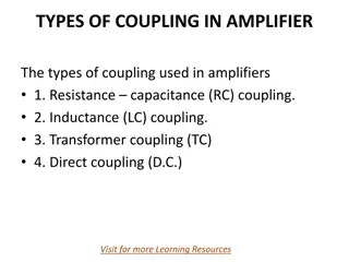
Types OF MULTISTAGE TRANSISTOR
AMPLIFIER
a)
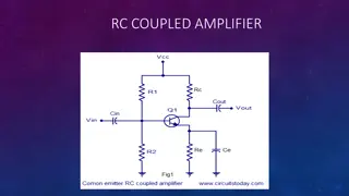
R-C coupled amplifier
b) Transformer coupled amplifier
c) Direct coupled amplifier
R.C.Coupling
•
In RC coupling, a capacitor is used as the
coupling device. The capacitor connects the
output of one stage to the input of the next
stage in order to pass the a.c. signal on while
blocking the d.c. bias voltages.
Transformer coupling
•
In transformer coupling, transformer is used
as the coupling device.
•
The transformer coupling provides the same
two functions but permits in addition
impedance matching.
Direct coupling
•
In direct coupling or d.c. coupling,
The individual amplifier stage bias conditions
are so designed that the two stages may be
directly connected without the necessity for
d.c. isolation.
Effect of Coupling and Bypass
Capacitors
•
Coupling capacitors
(or dc
blocking
capacitors
) are use to decouple ac
and dc signals so as not to disturb the
quiescent point of the circuit when ac signals
are injected at the input.
Bypass
capacitors
are used to force signal currents
around elements by providing a low
impedance path at the frequency.
•
A
coupling capacitor
is a
capacitor
which is
used to couple or link together only the AC
signal from one circuit element to another.
The
capacitor
blocks the DC signal from
entering the second element and, thus, only
passes the AC signal.
Bypass Capacitor
•
A
Bypass Capacitor
is usually applied between
the VCC and GND pins of an integrated circuit.
•
The
Bypass Capacitor
eliminates the
effect
of
voltage spikes on the power supply and also
reduce the power supply noise.
•
The name
Bypass Capacitor
is used as it
bypasses the high frequency components of
power supply
•
Coupling and Bypass Capacitors Coupling
capacitors (or dc blocking capacitors) are use
to decouple ac and dc signals so as not to
disturb the quiescent point of the circuit when
ac signals are injected at the input.
•
Bypass capacitors are used to force signal
currents around elements by providing a low
impedance path at the frequency.
Coupling and Bypass Capacitors
Explore the concept of multistage amplifiers in electronics circuits, where several amplifiers are arranged in a cascaded manner to increase gain and reduce distortion. Learn about the benefits, applications, and differences between cascade and cascode amplifiers in this informative guide.

Download Presentation

Please find below an Image/Link to download the presentation.
The content on the website is provided AS IS for your information and personal use only. It may not be sold, licensed, or shared on other websites without obtaining consent from the author. Download presentation by click this link. If you encounter any issues during the download, it is possible that the publisher has removed the file from their server.
E N D
Presentation Transcript
Electronics Circuits ECE-S 301
UNIT-1 Multistage Amplifiers
Definition An several amplifiers in cascaded arrangement such that output of one amplifier becomes the input of other whose output becomes input of next and so on . The overall voltage amplifier is product of voltage gain of individual amplifier amplifier formed by connecting gain of multistage
Why do we need multistage amplifier? The amplifier are flexibility within input & output impedance and higher gain. The multistage amplifier applications are, it can be used to increase extremely weak signals to utilizable levels. The distortion can be reduced by changing the signal within stages. advantages of the multistage
MULTISTAGE TRANSISTOR AMPLIFIER A transistor circuit containing more than one stage of amplification is known as multistage transistor amplifier. Block diagram of a 3-stage amplifier In a multistage amplifier, a number of single amplifiers are connected.
What is the difference between Cascade and cascode amplifier? From a transistor perspective, a cascade is typically when the amplifier load(s) are connected in a left-to right horizontal chain configuration, whereas a cascode has the load(s) stacked vertically. . Cascode: An amplifier consisting of a common emitter input stage that drives a common base output stage.
cascade amplifier A cascade amplifier is any two-port network constructed from a series of amplifiers, where each amplifier sends its output to the input of the next amplifier in a daisy chain. The complication in calculating the gain of cascaded stages is the non-ideal coupling between stages due to loading.
In an amplifier chain when the individual amplifiers are cascaded it means the output of the first amplifying device is connected to the input of the next and so on. Cascading is a general term for objects connected serially that start a chain reaction. A cascode on the other hand is an amplifying device that has a CE input stage driving a CB output stage.
Circuit of cascode amplifier Such cascade and cas code connection is also possible with FET amplifiers
Types OF MULTISTAGE TRANSISTOR AMPLIFIER a) R-C coupled amplifier b) Transformer coupled amplifier c) Direct coupled amplifier
R.C.Coupling In RC coupling, a capacitor is used as the coupling device. The capacitor connects the output of one stage to the input of the next stage in order to pass the a.c. signal on while blocking the d.c. bias voltages.
Transformer coupling In transformer coupling, transformer is used as the coupling device. The transformer coupling provides the same two functions but permits in addition impedance matching.
Direct coupling In direct coupling or d.c. coupling, The individual amplifier stage bias conditions are so designed that the two stages may be directly connected without the necessity for d.c. isolation.
Effect of Coupling and Bypass Capacitors Coupling blocking capacitors) are use to decouple ac and dc signals so as not to disturb the quiescent point of the circuit when ac signals are injected at capacitors are used to force signal currents around elements by providing a low impedance path at the frequency. capacitors (or dc the input. Bypass
A coupling capacitor is a capacitor which is used to couple or link together only the AC signal from one circuit element to another. The capacitor blocks the DC signal from entering the second element and, thus, only passes the AC signal.
Bypass Capacitor A Bypass Capacitor is usually applied between the VCC and GND pins of an integrated circuit. The Bypass Capacitor eliminates the effect of voltage spikes on the power supply and also reduce the power supply noise. The name Bypass Capacitor is used as it bypasses the high frequency components of power supply
Coupling and Bypass Capacitors Coupling capacitors (or dc blocking capacitors) are use to decouple ac and dc signals so as not to disturb the quiescent point of the circuit when ac signals are injected at the input. Bypass capacitors are used to force signal currents around elements by providing a low impedance path at the frequency.