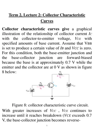
Understanding RC Coupled Amplifiers and Transistor Basics

Amplification is the process of increasing signal strength without changing its characteristics. An RC coupled amplifier is a multistage amplifier using resistors and capacitors. Transistor amplifiers amplify signals based on transistors with different configurations. The common emitter configuration is widely used in audio applications due to its positive gain and high input impedance. Operational amplifiers can also serve as amplification tools. Learn about the basic principles, circuit explanations, and parameters of transistors in amplifier circuits.
- RC Coupled Amplifiers
- Transistor Basics
- Amplification Process
- Common Emitter Configuration
- Multistage Amplifiers

Download Presentation

Please find below an Image/Link to download the presentation.
The content on the website is provided AS IS for your information and personal use only. It may not be sold, licensed, or shared on other websites without obtaining consent from the author. Download presentation by click this link. If you encounter any issues during the download, it is possible that the publisher has removed the file from their server.
E N D
Presentation Transcript
WHAT IS AMPLIFICATION Amplification is a process of increasing the signal strength by increasing the amplitude of a given signal without changing its characteristics. An RC coupled amplifier is a part of a multistage amplifier wherein different stages of amplifiers are connected using a combination of a resistor and a capacitor. An amplifier circuit is one of the basic circuits in electronics.
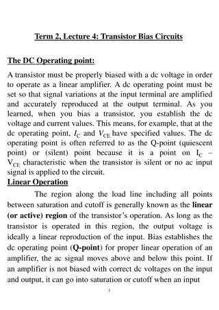
BASIC PRINCIPLE OF TRANSISTOR AMPLIFIER An amplifier that is completely based on the transistor is basically known as a transistor amplifier. The input signal may be a current signal, voltage signal, or a power signal. An amplifier will amplify the signal without changing its characteristics and the output will be a modified version of the input signal. Applications of amplifiers are of a wide range. They are mainly used in audio and video instruments, communications, controllers, etc.
CIRCUIT EXPLONATION input AC. the signal is applied to the base of the transistor of the 1ststage of RC coupled amplifier, from the function generator, it is then amplified across the output of the 1st stage. This amplified voltage is applied to the base of the next stage of the amplifier, through the coupling capacitor Cout where it is further amplified and reappears across the output of the second stage. Thus the successive stages amplify the signal and the overall gain is raised to the desired level. Much higher gain can be obtained by connecting a number of amplifier stages in succession. Resistance-capacitance (RC) coupling in amplifiers are most widely used to connect the output of first stage to the input (base) of the second stage and so on. This type of coupling is most popular because it is cheap and provides a constant amplification over a wide range of frequencies.
TRANSISTOR AS AMPLIFIER While knowing about different circuits for RC coupled amplifiers, it is important to know about transistors basics as amplifiers. The three configurations of the bipolar transistors that are commonly used are common base transistor (CB), common emitter transistor (CE), and common collector transistors (CE). Other than transistors, operational amplifiers can also be used for amplification purposes. Common emitter configuration is commonly used in the audio amplifier application because common-emitter has a gain that is positive and also greater than unity. In this configuration, the emitter is connected to ground and has high input impedance. Output impedance will be medium. Most of these types of transistor amplifier applications are commonly used in RF communication and optical fiber communications (OFC). The common base configuration has a gain less than unity. In this configuration, the collector is connected to the ground. We have low output impedance and high input impedance in the common base configuration.
BASIC PARAMETERS OF A TRANSISTOR (CE) Common collector configuration is also known as emitter follower because the input applied to the common emitter appears across the output of the common collector. In this configuration, the collector is connected to the ground. It has low output impedance and high input impedance. It has a gain almost equal to unity. Basic Parameters of a Transistor Amplifier We need to consider the following specifications before choosing the amplifier. A good amplifier must have all the following specifications: It should have a high input impedance It should have high stability It must have high linearity It should have high gain and bandwidth It must have high efficiency
THE RANGE OF FREQUENCY THAT AN AMPLIFIER CIRCUIT CAN AMPLIFY PROPERLY IS KNOWN AS THE BANDWIDTH OF THAT PARTICULAR AMPLIFIER. THE CURVE BELOW REPRESENTS THE FREQUENCY RESPONSE OF THE SINGLE- STAGE RC COUPLED AMPLIFIER.
BANDWIDTH The curve which represents the variation of gain of an amplifier with frequency is called the frequency response curve. The bandwidth is measured between the lower half power and upper half power points. P1 point is lower half power and P2 is upper half power respectively. A good audio amplifier must have a bandwidth from 20 Hz to 20 kHz because that is the frequency range that is audible.
GAIN Gain: The gain of an amplifier is defined as the ratio of output power to the input power. Gain can be expressed either in decibel (dB) or in numbers. The gain represents how much an amplifier is able to amplify a signal given to it. The below equation represents a gain in number: G= Pout/Pin Where Pout is the output power of an amplifier The pin is the input power of an amplifier The equation below represents a gain in decibel (DB): Gain in DB= 10log (Pout/Pin) Gain can also be expressed in voltage and current. The gain in voltage is the ratio of the output voltage to the input voltage and gain in current is ratio of output current to the input current. The equation for gain in voltage and current is shown below
HIGH INPUT IMPEDANCE Gain in voltage= output voltage/ input voltage Gain in current= output current/ input current High Input Impedance: Input impedance is the impedance that is offered by an amplifier circuit when it is connected to the voltage source. The transistor amplifier must have high input impedance in order to prevent it from loading the input voltage source. So that is the reason for having high impedance in the amplifier. Noise: Noise refers to unwanted fluctuation or frequencies present in a signal. It may be due to the interaction between two or more signals present in a system, component failures, design flaws, external interference, or maybe by virtue of certain components used in the amplifier circuit.
EFFICIENCY Efficiency: The Efficiency of an amplifier represents how an amplifier can utilize the power supply efficiently. And also measures how much power from the power supply is gainfully converted at the output. Efficiency is usually expressed in percentage and the equation for efficiency is given as (Pout/ Ps) x 100. Where Pout is the power output and Ps is the power drawn from the power supply. A Class A transistor amplifier has 25% efficiency and provides excellent signal reproduction but the efficiency is very low. Class C amplifier has efficiency up to 90%, but the signal reproduction is bad. Class AB stands in between class A and class C amplifiers so it is commonly used in audio amplifier applications. This amplifier has an efficiency of up to 55%. Slew Rate: The slew rate of an amplifier is the maximum rate of change of output per unit time. It represents how rapidly the output of an amplifier can be changed in response to change in the input
STABILITY Stability: Stability is the capacity of an amplifier to resist oscillations. Usually, stability problems occur during high-frequency operations, close to 20 kHz in case of audio amplifiers. The oscillations may be of high or low amplitude.
FREQUENCY RESPONSE OF RC COUPLED AMPLIFIER Frequency Response of RC Coupled Amplifier Frequency response curve is a graph that indicates the relationship between voltage gain and function of freq
LOW FREQUENCY (BELOW 50 HZ) At Low frequencies (i.e. below 50 Hz) The capacitive reactance is inversely proportional to the frequency. At low frequencies, the reactance is quite high. The reactance of input capacitor Cinand the coupling capacitor CCare so high that only small part of the input signal is allowed. The reactance of the emitter by pass capacitor CEis also very high during low frequencies. Hence it cannot shunt the emitter resistance effectively. With all these factors, the voltage gain rolls off at low frequencies.
HIGH FREQUENCY (ABOVE 20 KHZ) At High frequencies (i.e. above 20 KHz) Again considering the same point, we know that the capacitive reactance is low at high frequencies. So, a capacitor behaves as a short circuit, at high frequencies. As a result of this, the loading effect of the next stage increases, which reduces the voltage gain. Along with this, as the capacitance of emitter diode decreases, it increases the base current of the transistor due to which the current gain ( ) reduces. Hence the voltage gain rolls off at high frequencies.
MID FREQUENCY (50HZ TO 20KHZ) At Mid-frequencies (i.e. 50 Hz to 20 KHz) The voltage gain of the capacitors is maintained constant in this range of frequencies, as shown in figure. If the frequency increases, the reactance of the capacitor CCdecreases which tends to increase the gain. But this lower capacitance reactive increases the loading effect of the next stage by which there is a reduction in gain. Due to these two factors, the gain is maintained constant.
ADVANTAGES OF RC COUPLED AMPLIFIER The following are the advantages of RC coupled amplifier. The frequency response of RC amplifier provides constant gain over a wide frequency range, hence most suitable for audio applications. The circuit is simple and has lower cost because it employs resistors and capacitors which are cheap. It becomes more compact with the upgrading technology.
DISADVANTAGE OF RC COUPLED AMPLIFIER . The voltage and power gain are low because of the effective load resistance. They become noisy with age. Due to poor impedance matching, power transfer will be low.
APPLICATIONS OF RC COUPLED AMPLIFIER The following are the applications of RC coupled amplifier. They have excellent audio fidelity over a wide range of frequency. Widely used as Voltage amplifiers Due to poor impedance matching, RC coupling is rarely used in the final stages.
APPLICATIONS OF RC COUPLED AMPLIFIER applications of the RC coupled amplifier are as follows: 1. Based on the frequency response of the RC coupled amplifier the gain remains constant to the maximum extent for the frequencies applied. Hence this makes this amplifier to be suitable for amplification of the audio signals. 2. These amplifiers are preferred as Preamplifiers. 3. This amplifier is also widely used in the amplification of the voltage signals.


")
")


")
")
")