Understanding Phase Difference and Phase Shift in Sinusoidal Waveforms
Phase difference and phase shift describe the angular displacement of sinusoidal waveforms in degrees or radians. These concepts are crucial in analyzing the relationship between alternating quantities such as voltage and current. The phase angle determines the shift of a waveform along the horizontal zero axis, impacting its behavior and alignment with other waveforms. By understanding phase relationships, engineers can optimize circuit performance and signal processing.
Download Presentation

Please find below an Image/Link to download the presentation.
The content on the website is provided AS IS for your information and personal use only. It may not be sold, licensed, or shared on other websites without obtaining consent from the author. Download presentation by click this link. If you encounter any issues during the download, it is possible that the publisher has removed the file from their server.
E N D
Presentation Transcript
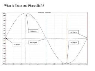
Phase Difference and Phase Shift Phase Difference is used to describe the difference in degrees or radians when two or more alternating quantities reach their maximum or zero values Previously we saw that a Sinusoidal Waveform is an alternating quantity that can be presented graphically in the time domain along an horizontal zero axis. We also saw that as an alternating quantity, sine waves have a positive maximum value at time /2, a negative maximum value at time 3 /2, with zero values occurring along the baseline at 0, and 2 . However, not all sinusoidal waveforms will pass exactly through the zero axis point at the same time, but may be shifted to the right or to the left of 0oby some value when compared to another sine wave. For example, comparing a voltage waveform to that of a current waveform. This then produces an angular shift or Phase Difference between the two sinusoidal waveforms. Any sine wave that does not pass through zero at t = 0 has a phase shift.
The phase difference or phase shift as it is also called of a Sinusoidal Waveform is the angle (Greek letter Phi), in degrees or radians that the waveform has shifted from a certain reference point along the horizontal zero axis. In other words phase shift is the lateral difference between two or more waveforms along a common axis and sinusoidal waveforms of the same frequency can have a phase difference. The phase difference, of an alternating waveform can vary from between 0 to its maximum time period, T of the waveform during one complete cycle and this can be anywhere along the horizontal axis between, = 0 to 2 (radians) or = 0 to 360o depending upon the angular units used. Phase difference can also be expressed as a time shift of in seconds representing a fraction of the time period, T for example, +10mS or 50uS but generally it is more common to express phase difference as an angular measurement. Then the equation for the instantaneous value of a sinusoidal voltage or current waveform we developed in the previous Sinusoidal Waveform will need to be modified to take account of the phase angle of the waveform and this new general expression becomes.
Phase Difference Equation Where: Am is the amplitude of the waveform. t is the angular frequency of the waveform in radian/sec. (phi) is the phase angle in degrees or radians that the waveform has shifted either left or right from the reference point. If the positive slope of the sinusoidal waveform passes through the horizontal axis before t = 0 then the waveform has shifted to the left so >0, and the phase angle will be positive in nature, + giving a leading phase angle. In other words it appears earlier in time than 0oproducing an anticlockwise rotation of the vector. Likewise, if the positive slope of the sinusoidal waveform passes through the horizontal x-axis some time after t = 0 then the waveform has shifted to the right so <0, and the phase angle will be negative in nature - producing a lagging phase angle as it appears later in time than 0oproducing a clockwise rotation of the vector. Both cases are shown below.
Phase Relationship of a Sinusoidal Waveform Firstly, lets consider that two alternating quantities such as a voltage, v and a current, i have the same frequency in Hertz. As the frequency of the two quantities is the same the angular velocity, must also be the same. So at any instant in time we can say that the phase of voltage, v will be the same as the phase of the current, i.
Then the angle of rotation within a particular time period will always be the same and the phase difference between the two quantities of v and i will therefore be zero and = 0. As the frequency of the voltage, v and the current, i are the same they must both reach their maximum positive, negative and zero values during one complete cycle at the same time (although their amplitudes may be different). Then the two alternating quantities, v and i are said to be in- phase . Two Sinusoidal Waveforms in-phase
Now lets consider that the voltage, v and the current, i have a phase difference between themselves of 30o, so ( = 30oor /6 radians). As both alternating quantities rotate at the same speed, i.e. they have the same frequency, this phase difference will remain constant for all instants in time, then the phase difference of 30obetween the two quantities is represented by phi, as shown below. Phase Difference of a Sinusoidal Waveform
The voltage waveform above starts at zero along the horizontal reference axis, but at that same instant of time the current waveform is still negative in value and does not cross this reference axis until 30olater. Then there exists a Phase difference between the two waveforms as the current cross the horizontal reference axis reaching its maximum peak and zero values after the voltage waveform. As the two waveforms are no longer in-phase , they must therefore be out-of- phase by an amount determined by phi, and in our example this is 30o. So we can say that the two waveforms are now 30oout-of phase. The current waveform can also be said to be lagging behind the voltage waveform by the phase angle, . Then in our example above the two waveforms have a Lagging Phase Difference so the expression for both the voltage and current above will be given as. where, i leads v by angle
The phase angle of a sine wave can be used to describe the relationship of one sine wave to another by using the terms Leading and Lagging to indicate the relationship between two sinusoidal waveforms of the same frequency, plotted onto the same reference axis. In our example above the two waveforms are out-of- phase by 30o. So we can correctly say that i lags v or we can say that v leads i by 30odepending upon which one we choose as our reference. The relationship between the two waveforms and the resulting phase angle can be measured anywhere along the horizontal zero axis through which each waveform passes with the same slope direction either positive or negative. In AC power circuits this ability to describe the relationship between a voltage and a current sine wave within the same circuit is very important and forms the bases ofAC circuit analysis.
The Cosine Waveform So we now know that if a waveform is shifted to the right or left of 0owhen compared to another sine wave the expression for this waveform becomes Amsin( t ). But if the waveform crosses the horizontal zero axis with a positive going slope 90oor /2 radians before the reference waveform, the waveform is called a Cosine Waveform and the expression becomes. The Cosine Wave, simply called cos , is as important as the sine wave in electrical engineering. The cosine wave has the same shape as its sine wave counterpart that is it is a sinusoidal function, but is shifted by +90oor one full quarter of a period ahead of it. Phase Difference between a Sine wave and a Cosine wave
Alternatively, we can also say that a sine wave is a cosine wave that has been shifted in the other direction by -90o. Either way when dealing with sine waves or cosine waves with an angle the following rules will always apply. Sine and Cosine Wave Relationships When comparing two sinusoidal waveforms it more common to express their relationship as either a sine or cosine with positive going amplitudes and this is achieved using the following mathematical identities.
By using these relationships above we can convert any sinusoidal waveform with or without an angular or phase difference from either a sine wave into a cosine wave or vice versa. In the next tutorial about Phasors we will use a graphical method of representing or comparing the phase difference between two sinusoids by looking at the phasor representation of a single phase AC quantity along with some phasor algebra relating to the mathematical addition of two or more phasors
Phasor Diagrams and PhasorAlgebra Phasor Diagrams are a graphical way of representing the magnitude and directional relationship between two or more alternating quantities Sinusoidal waveforms of the same frequency can have a Phase Difference between themselves which represents the angular difference of the two sinusoidal waveforms. Also the terms lead and lag as well as in-phase and out-of-phase are commonly used to indicate the relationship of one waveform to the other with the generalized sinusoidal expression given as: A(t)=Amsin( t ) representing the sinusoid in the time-domain form. But when presented mathematically in this way it is sometimes difficult to visualise this angular or phasor difference between two or more sinusoidal waveforms. One way to overcome this problem is to represent the sinusoids graphically within the spacial or phasor-domain form by using Phasor Diagrams, and this is achieved by the rotating vector method.
Basically a rotating vector, simply called a Phasor is a scaled line whose length represents an AC quantity that has both magnitude ( peak amplitude ) and direction ( phase ) which is frozen at some point in time. A phasor is a vector that has an arrow head at one end which signifies partly the maximum value of the vector quantity ( V or I ) and partly the end of the vector that rotates. Generally, vectors are assumed to pivot at one end around a fixed zero point known as the point of origin while the arrowed end representing the quantity, freely rotates in an anti-clockwise direction at an angular velocity, ( ) of one full revolution for every cycle. This anti-clockwise rotation of the vector is considered to be a positive rotation. Likewise, a clockwise rotation is considered to be a negative rotation. Although the both the terms vectors and phasors are used to describe a rotating line that itself has both magnitude and direction, the main difference between the two is that a vectors magnitude is the peak value of the sinusoid while a phasors magnitude is the rms value of the sinusoid. In both cases the phase angle and direction remains the same.
The phase of an alternating quantity at any instant in time can be represented by a phasor diagram, so phasor diagrams can be thought of as functions of time . A complete sine wave can be constructed by a single vector rotating at an angular velocity of = 2 , where is the frequency of the waveform. Then a Phasor is a quantity that has both Magnitude and Direction . Generally, when constructing a phasor diagram, angular velocity of a sine wave is always assumed to be: in rad/sec. Consider the phasor diagram below. Phasor Diagram of a Sinusoidal Waveform
As the single vector rotates in an anti-clockwise direction, its tip at point A will rotate one complete revolution of 360oor 2 representing one complete cycle. If the length of its moving tip is transferred at different angular intervals in time to a graph as shown above, a sinusoidal waveform would be drawn starting at the left with zero time. Each position along the horizontal axis indicates the time that has elapsed since zero time, t = 0. When the vector is horizontal the tip of the vector represents the angles at 0o, 180oand at 360o. Likewise, when the tip of the vector is vertical it represents the positive peak value, ( +Am ) at 90oor /2 and the negative peak value, ( -Am ) at 270oor 3 /2. Then the time axis of the waveform represents the angle either in degrees or radians through which the phasor has moved. So we can say that a phasor represent a scaled voltage or current value of a rotating vector which is frozen at some point in time, ( t ) and in our example above, this is at an angle of 30o.
Sometimes when we are analysing alternating waveforms we may need to know the position of the phasor, representing the Alternating Quantity at some particular instant in time especially when we want to compare two different waveforms on the same axis. For example, voltage and current. We have assumed in the waveform above that the waveform starts at time t = 0 with a corresponding phase angle in either degrees or radians. But if a second waveform starts to the left or to the right of this zero point or we want to represent in phasor notation the relationship between the two waveforms then we will need to take into account this phase difference, of the waveform. Consider the diagram below from the previous Phase Difference tutorial.
Phase Difference of a Sinusoidal Waveform The generalised mathematical expression to define these two sinusoidal quantities will be written as:
The current, i is lagging the voltage, v by angle and in our example above this is 30o. So the difference between the two phasors representing the two sinusoidal quantities is angle and the resulting phasor diagram will be. Phasor Diagram of a Sinusoidal Waveform The phasor diagram is drawn corresponding to time zero ( t = 0 ) on the horizontal axis. The lengths of the phasors are proportional to the values of the voltage, ( V ) and the current, ( I ) at the instant in time that the phasor diagram is drawn. The current phasor lags the voltage phasor by the angle, , as the two phasors rotate in an anticlockwise direction as stated earlier, therefore the angle, is also measured in the same anticlockwise direction.
If however, the waveforms are frozen at time, t = 30o, the corresponding phasor diagram would look like the one shown on the right. Once again the current phasor lags behind the voltage phasor as the two waveforms are of the same frequency. However, as the current waveform is now crossing the horizontal zero axis line at this instant in time we can use the current phasor as our new reference and correctly say that the voltage phasor is leading the current phasor by angle, . Either way, one phasor is designated as the reference phasor and all the other phasors will be either leading or lagging with respect to this reference.
PhasorAddition Sometimes it is necessary when studying sinusoids to add together two alternating waveforms, for example in an AC series circuit, that are not in-phase with each other. If they are in-phase that is, there is no phase shift then they can be added together in the same way as DC values to find the algebraic sum of the two vectors. For example, if two voltages of say 50 volts and 25 volts respectively are together in-phase , they will add or sum together to form one voltage of 75 volts (50 + 25). If however, they are not in-phase that is, they do not have identical directions or starting point then the phase angle between them needs to be taken into account so they are added together using phasor diagrams to determine their Resultant Phasor or Vector Sum by using the parallelogram law. Consider two AC voltages, V1having a peak voltage of 20 volts, and V2having a peak voltage of 30 volts where V1leads V2by 60o. The total voltage, VTof the two voltages can be found by firstly drawing a phasor diagram representing the two vectors and then constructing a parallelogram in which two of the sides are the voltages, V1and V2 as shown below.
PhasorAddition of two Phasors By drawing out the two phasors to scale onto graph paper, their phasor sum V1+ V2can be easily found by measuring the length of the diagonal line, known as the resultant r-vector , from the zero point to the intersection of the construction lines 0-A. The downside of this graphical method is that it is time consuming when drawing the phasors to scale.
Also, while this graphical method gives an answer which is accurate enough for most purposes, it may produce an error if not drawn accurately or correctly to scale. Then one way to ensure that the correct answer is always obtained is by an analytical method. Mathematically we can add the two voltages together by firstly finding their vertical and horizontal directions, and from this we can then calculate both the vertical and horizontal components for the resultant r vector , VT. This analytical method which uses the cosine and sine rule to find this resultant value is commonly called the Rectangular Form. In the rectangular form, the phasor is divided up into a real part, x and an imaginary part, y forming the generalised expression Z = x jy. ( we will discuss this in more detail in the next tutorial ). This then gives us a mathematical expression that represents both the magnitude and the phase of the sinusoidal voltage as:
Definition of a Complex Sinusoid So the addition of two vectors, A and B using the previous generalised expression is as follows: PhasorAddition using Rectangular Form Voltage, V2of 30 volts points in the reference direction along the horizontal zero axis, then it has a horizontal component but no vertical component as follows. Horizontal Component = 30 cos 0o= 30 volts Vertical Component = 30 sin 0o= 0 volts This then gives us the rectangular expression for voltage V2of: 30 + j0 Voltage, V1of 20 volts leads voltage, V2by 60o, then it has both horizontal and vertical components as follows.
Horizontal Component = 20 cos 60o= 20 x 0.5 = 10 volts Vertical Component = 20 sin 60o= 20 x 0.866 = 17.32 volts This then gives us the rectangular expression for voltage V1of: 10 + j17.32 The resultant voltage, VTis found by adding together the horizontal and vertical components as follows. VHorizontal= sum of real parts of V1and V2= 30 + 10 = 40 volts VVertical= sum of imaginary parts of V1and V2= 0 + 17.32 = 17.32 volts Now that both the real and imaginary values have been found the magnitude of voltage, VTis determined by simply using Pythagoras s Theorem for a 90otriangle as follows.
Phasor Subtraction Phasor subtraction is very similar to the above rectangular method of addition, except this time the vector difference is the other diagonal of the parallelogram between the two voltages of V1and V2as shown. Vector Subtraction of two Phasors
This time instead of adding together both the horizontal and vertical components we take them away, subtraction.
