Understanding Electrical Principles in Industrial Electronics
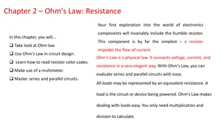
Explore the fundamentals of industrial electronics, starting with direct current principles related to atomic theory, conductors, insulators, and resistors in series and parallel. Then, delve into alternating current principles, including generating an alternating voltage, alternating current (AC) behavior, and analyzing AC circuits with resistance, inductance, and capacitance effects. Gain insights into the essential concepts that form the basis of industrial electronics.
Download Presentation

Please find below an Image/Link to download the presentation.
The content on the website is provided AS IS for your information and personal use only. It may not be sold, licensed, or shared on other websites without obtaining consent from the author. Download presentation by click this link. If you encounter any issues during the download, it is possible that the publisher has removed the file from their server.
E N D
Presentation Transcript
Module 1: Direct current principles ATOMIC THEORY An atom could be defined as the smallest part of an element that retains the property of the element. The three main parts are made up of: Protons (positively charged); Neutrons (no electrical charge); and Tiny electrons (negatively charged). www.futuremanagers.com
Module 1: Direct current principles (continued) DIRECT CURRENT PRINCIPLES Electrically, materials are classified as: Conductors: When valency electrons are easily removed from their valency bands to be utilised for conduction purposes. Insulators: When valency electrons are not easily removed from their valency bands. Semi-conductors: Subjected to certain conditions, these elements can be considered to be either conductors or insulators. www.futuremanagers.com
Module 1: Direct current principles (continued) RESISTORS IN SERIES, PARALLEL, AND SERIES-PARALLEL Resistors can be arranged in: Series: Parallel: And a combination of series-parallel. www.futuremanagers.com
Module 2: Alternating current principles GENERATING AN ALTERNATING VOLTAGE When a conductor cuts through the lines of magnetic force between two opposite poles of a magnet, a voltage is induced in the conductor. This is the principle of operation of an elementary electric generator and it is used to generate an AC voltage. www.futuremanagers.com
Module 2: Alternating current principles (continued) ALTERNATING CURRENT (AC) When a voltage of alternating magnitude is connected across a load, a current of alternating magnitude, is generated as a representation of the current flowing in the circuit. www.futuremanagers.com
Module 2: Alternating current principles (continued) AC CIRCUITS CONTAINING R, L AND C COMPONENTS In order to use effective values of voltage and current in any AC circuit, the effect of resistance (R), inductance (L) and capacitance (C) must be considered. The combined effect of the resistance (R), inductive reactance (??) and capacitive reactance (??) together makes up the total opposition to current flow in an AC circuit. www.futuremanagers.com
Module 3: Measuring instruments: Analogue and digital meters THE MOVING-COIL METER The basic moving-coil meter in can be used for measuring DC voltages and DC currents as well as resistance. www.futuremanagers.com
Module 3: Measuring instruments: Analogue and digital meters (continued) DAMPING MECHANISMS Galvanometer damping is provided by two mechanisms: Mechanical which is caused mainly by the motion of the coil through the air surrounding it; and Electromagnetic which is caused by induced effects in the moving coil as it rotates in the magnetic field, provided that the coil forms part of a closed electrical circuit. www.futuremanagers.com
Module 3: Measuring instruments: Analogue and digital meters (continued) THE AVO METER An AVO meter is an indicating device determining specific electrical quantities, most commonly Amperes, Volts and Ohms. www.futuremanagers.com
Module 3: Measuring instruments: Analogue and digital meters (continued) METER USES The meter can be used as: An Ammeter, which must be connected in series with the load; A Voltmeter, which must be connected in parallel with the load; and An Ohmmeter, which must also be connected in parallel with the load. www.futuremanagers.com
Module 3: Measuring instruments: Analogue and digital meters (continued) SAFETY PRECAUTIONS AND HANDLING Read the operating instructions before using a multimeter. Although these meters are relatively robust, well-constructed and manufactured, negligence and carelessness can easily damage the instrument. Pay attention to the correct settings, connections and polarity when using the instrument. www.futuremanagers.com
Module 4: Synchro and servo systems INTRODUCTION A simple Synchro system can be thought of as the electrical equivalent of a long metal shaft that transmits motion from one point to another. For example, when one end of the shaft is being rotated mechanically, the other end turns in exactly the same manner. www.futuremanagers.com
Module 4: Synchro and servo systems (continued) SYNCHRO MOTOR (TRANSMITTER) A typical Synchro motor may have up to five conductors coming out of its housing (two for the rotor and three for the starter). www.futuremanagers.com
Module 4: Synchro and servo systems (continued) APPLICATIONS www.futuremanagers.com
Module 4: Synchro and servo systems (continued) PRINCIPLE OF OPERATION Lenz s Law can be defined as a magnetic field that cuts through a coil to induce a voltage in that coil, which causes a current to flow. This induced current will in turn generate its own magnetic field, which will oppose the original inducing magnetic field. www.futuremanagers.com
Module 4: Synchro and servo systems (continued) SYNCHRO TRANSMITTER-RECENER CONNECTIONS The Synchro transmitter can be connected in the following ways: As a Synchro transmitter-indicator team; As a Synchro transmitter-indicator system with reverse rotation; As a Synchro system with 180 phase shift; and As a Synchro system with 240 phase shift. www.futuremanagers.com
Module 4: Synchro and servo systems (continued) ADVANTAGES OF SYNCHRO SYSTEMS TO MECHANICAL SYSTEMS No friction losses between sender and receiver; Utilises very little electrical energy; Small and light since data transfer is by means of electrical conductors; Transmission can take place around bends without modifications; Connection between transmitter and receiver can be by means of conductors, infrared light, radar, radio frequency and micro moves; and In limited cases, flexible metal shafts are used. www.futuremanagers.com
Module 4: Synchro and servo systems (continued) SYNCHRO SYSTEMS VS SERVO SYSTEMS When a Synchro system is redesigned with the appropriate servo motors, servo amplifiers and feedback systems to accommodate larger currents, torque and heavier loads (such as a gear train); then the Synchro system is referred to as a servo system. www.futuremanagers.com
Module 5: Transducer devices INTRODUCTION A transducer can be defined as a device that converts one form of energy into another form of energy. www.futuremanagers.com
Module 5: Transducer devices (continued) THERMISTORS Thermistors are non-linear resistors that are extremely sensitive to temperature changes, exhibiting either PTC or NTC. Thermistors applications include: Measurement and control of temperature (furnaces and kilns); Temperature compensation; Liquid level indicators; and Time delay devices. www.futuremanagers.com
Module 5: Transducer devices (continued) THERMOCOUPLES Thermocouples are also temperature sensitive transducer devices. These devices are extremely accurate and are employed in industries such as the aircraft industry to monitor the exhaust gas temperature of a turbine engine. www.futuremanagers.com
Module 5: Transducer devices (continued) BIMETAL STRIPS The bimetal strip is probably the most common and widely used device to detect thermal change. Bimetal applications include features in: The motor vehicle industry; Domestic appliances, such as the refrigerator; Hot-water tank temperature control; Electrical power control; and Gas-operated appliances. www.futuremanagers.com
Module 5: Transducer devices (continued) LIGHT-DEPENDENT RESISTORS (LDR) Light-dependent resistors have a variety of uses in the various industries but, due to their relative slow response times (around 6 7 m seconds) their use is generally limited to relatively slow-moving objects such as counting bottles, cans or any other similar product in various industries. www.futuremanagers.com
Module 6: The decibel INTRODUCTION The term (or unit) decibel, abbreviated as dB, is named after Alexander Graham Bell who first applied the logarithmic principle to measurements he performed during experiments of deafness. The decibel can be mathematically defined as: ??????? ?????? ???= 10log ?? www.futuremanagers.com
Module 6: The decibel (continued) TRANSMISSION LINES Any wire or conductor can be considered a transmission line. When considering microwave frequencies, coaxial cable and parallel wires generate rather great losses and we have to use another form of transmission line such as waveguides and fibre optics. www.futuremanagers.com
Module 6: The decibel (continued) CHARACTERISTIC IMPEDANCE The characteristic impedance is the ratio of the voltage to the current of a wave travelling in either direction on a transmission line (implying that the input and output impedances is common to the line). www.futuremanagers.com
Module 6: The decibel (continued) CURRENT RATIOS By definition, we can see that the gain (or loss) of a network or transmission line is not merely expressed in terms of power (watts), but it can also be expressed in terms of current or voltage. www.futuremanagers.com
Module 6: The decibel (continued) CONCLUSION The gain or loss of a network can be expressed as being a ratio between the output and input of the system in terms its power (watts) voltage or current expressed in decibel (dB). Although the decibel is not an absolute unit, it indicates the relationship between two powers. www.futuremanagers.com
Module 7: Semi-conductor diodes INTRODUCTION All materials exhibit certain resistive characteristics when analysed at room temperature. Materials can be divided electrically into three main groups: Conductors; Insulators; and Semi-conductors. www.futuremanagers.com
Module 7: Semi-conductor diodes (continued) ENERGY LEVELS The resistance of a semi-conductor material is greater than that of a conductor, but considerably less than that of an insulator. The energy-band diagram expresses the relationship between conductors, semi-conductors, and insulators: www.futuremanagers.com
Module 7: Semi-conductor diodes (continued) DOPING The method of adding impurities to pure Si or Ge to make it a better conductor of electron flow is called doping. www.futuremanagers.com
Module 7: Semi-conductor diodes (continued) THE PN-JUNCTION A PN-junction is formed when a P-type material and an N-type material is joined together. This joining together is not an electrical junction but is a junction which is achieved through a manufacturing process in which electrons and holes are uniformly distributed in the two types of material provided they have been doped to the same extent. www.futuremanagers.com
Module 7: Semi-conductor diodes (continued) BIASING There is forward biasing: And reverse biasing: www.futuremanagers.com
Module 7: Semi-conductor diodes (continued) DIODE APPLICATIONS Junction diodes are extensively used for rectification purposes in a wide variety of industries. Other than their ability to supply half-wave or full-wave rectification of an AC quantity, diodes are also used as protection devices in inductive circuits and other types of loads. www.futuremanagers.com
Module 7: Semi-conductor diodes (continued) TYPES OF DIODES AVAILABLE Types of diodes available includes: PN-junction diodes; Point-contact diodes; Zener diodes; Photo diodes; Light-emitting diodes; and Varactor diodes. www.futuremanagers.com
Module 7: Semi-conductor diodes (continued) LIGHT-EMITTING DIODE (LED) A light-emitting diode will emit (give off) visible light when correctly biased and energised. Their area of operation is in the forward bias region when the recombination of holes and electrons within the junction region will release energy in the form of heat and photons. www.futuremanagers.com
Module 7: Semi-conductor diodes (continued) ZENER DIODE The zener diode is constructed so that it is mainly used in the reverse bias mode. When operated in the forward bias mode, however, its forward characteristics are similar to that of an ordinary junction diode. www.futuremanagers.com
Module 7: Semi-conductor diodes (continued) PHOTO DIODE A photo diode is a semi-conductor PN-junction device whose area of operation is restricted to the reverse bias region. www.futuremanagers.com
Module 7: Semi-conductor diodes (continued) VARACTER DIODE (VVC) The varactor diodes are semi-conductor, voltage-dependent, variable capacitors. Their mode of operation is determined by the capacitance that exists at the PN-junction when the device is reversed biased. www.futuremanagers.com
Module 8: Semi-conductor transistors TRANSISTOR CONSTRUCTION The transistor is a three-layer semiconductor device consisting of two PN- junctions arranged as: Two P-type and one N-type layer (called a PNP transistor); or Two N-type and one P-type layer (called a NPN transistor). www.futuremanagers.com
Module 8: Semi-conductor transistors (continued) TRANSISTOR BIASING The biasing potentials, ??? and ??? for both PNP- and NPN-type transistors can be seen: www.futuremanagers.com
Module 8: Semi-conductor transistors (continued) TRANSISTOR OPERATION the emitter supplies the majority carriers, which is in turn are being collected by the collector with the presence of a small base current. Applying Kirchoff s current law we get: ??= ??+ ?? which relates to the emitter current = the sum of the collector and base currents. www.futuremanagers.com
Module 8: Semi-conductor transistors (continued) TRANSISTOR CHARACTERISTIC CURVE Transistors are employed as being either an electronic switch or an amplifier. The characteristic curve seen below illustrates the various regions of operation for a transistor. www.futuremanagers.com
Module 8: Semi-conductor transistors (continued) TRANSISTOR AMPLIFIER CIRCUITS Since a transistor has three terminals, it can be connected in anyone of three configurations: Common base; Common emitter; and Common collector configuration. www.futuremanagers.com
Module 8: Semi-conductor transistors (continued) TRANSISTOR COMPARISON TABLE www.futuremanagers.com


