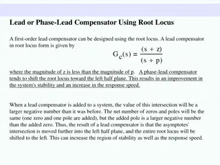
Understanding RC Phase Shift Oscillators
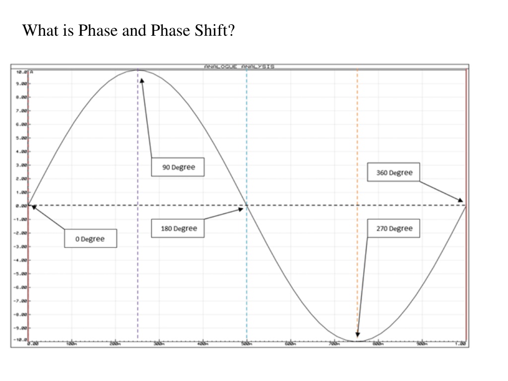

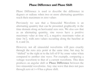
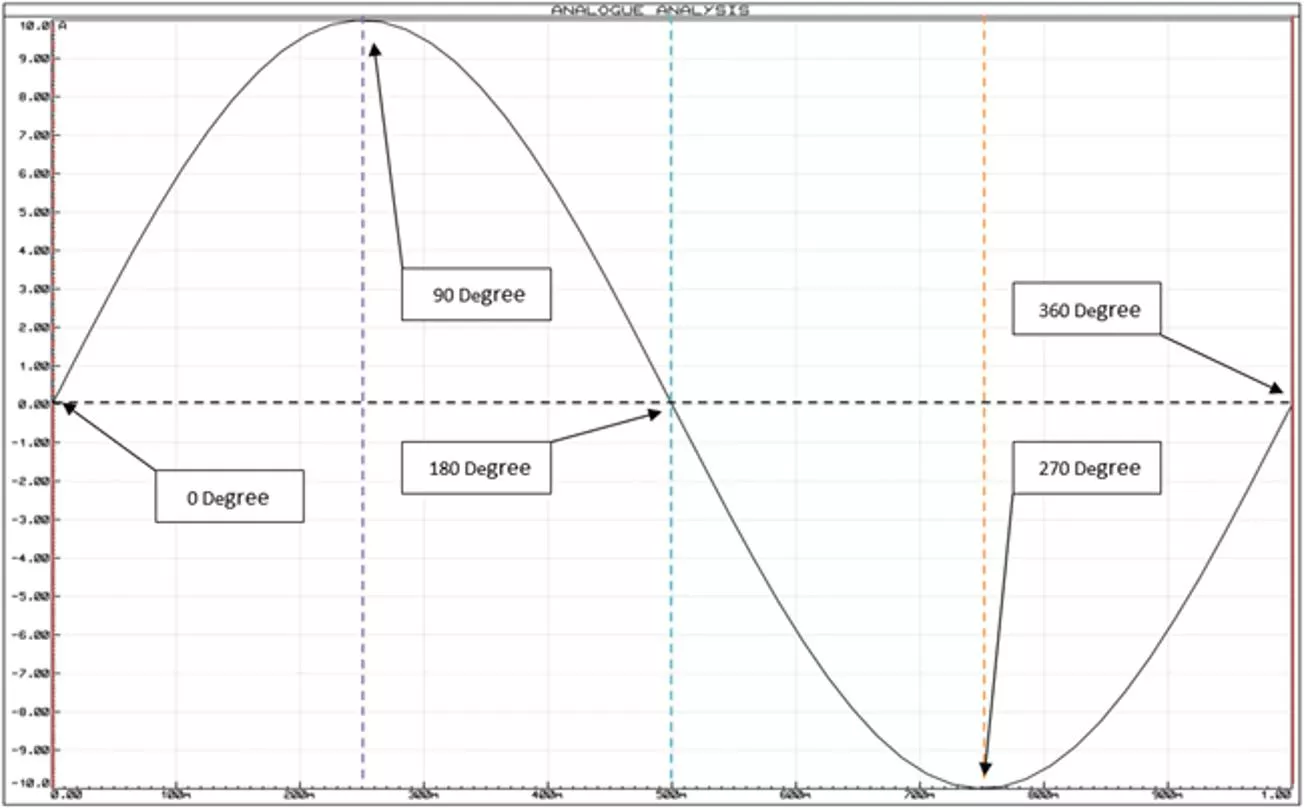
What is Phase and Phase Shift?
What is RC Phase Shift Oscillator?
RC phase-shift oscillator circuit can be built with a resistor as well
as a capacitor. This circuit offers the required phase shift with the
feedback signal. They have outstanding frequency strength and
can give a clean sine wave for an extensive range of loads.
Preferably an easy RC network can be expected to include an o/p
which directs the input
with 90
o
.
If we cascade there RC network, we will get
180-degree
phase
shift.
RC Phase-Shift Network
RC Phase Angle
Where: X
C
is the Capacitive Reactance of the capacitor,
R is the Resistance of the resistor, and ƒ is the
Frequency.
R-C phase shift
The total impedance of the circuit is,
The r.m.s. value of the input voltage applied is say V
i
volts.
Hence the current is given by,
From the expression of current, it can be seen that current I
leads input voltage
by angle
The output voltage
is the drop in resistance R given by,
The voltage across the capacitor is,
The drop
is in phase with current I while the drop V
c
lags
current
I
by 90° i.e. I leads V
c
by 90°.
By using proper values of R and C, the angle is adjusted in
practice equal to 60°.
RC Feedback Network
The RC network is used in the feedback path. In the
oscillator, the feedback network must introduce a phase shift
of 180° to obtain a total phase shift around a loop as 360°.
RC Phase Shift Oscillator Using Op-amp
R-C phase shift oscillator using op-amp uses an op-amp in
inverting amplifier mode
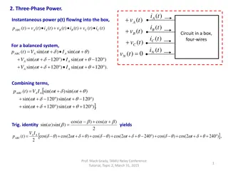
Find the transfer function of the RC feedback
network :
Applying KVL to various loops we get,
Replacing jω by s and writing the equations in the
matrix form,
Using the Crammer’s rule to obtain I
3
This is the frequency with which circuit oscillates,
ɷ=2πf
f= ɷ/2π
At this frequency,
The negative sign indicates a phase shift of
180
°
ɷ=2πf
f= ɷ/2π
Thus circuit will work as an oscillator which will produce a
sinusoidal waveform if the gain is 29 and total phase shift
around a loop is 360°. This satisfies the Barkhausen criterion
for the oscillator. These oscillators are used over the audio
frequency range i.e. about 20 Hz up to 100 kHz.
Advantages
The advantages of R-C phase shift oscillator are,
•
The circuit is simple to design.
•
Can produce output over the audio frequency range.
•
Produces sinusoidal output waveform. –
•
It is a fixed-frequency oscillator.
Disadvantages
By changing the values of R and C, the frequency of the
oscillator can be changed. But the values of R and C of all three
sections must be changed simultaneously to satisfy the oscillating
conditions. But this is practically impossible. Hence the phase
shift oscillator is considered as a fixed frequency oscillator, for all
practical purposes.
And the frequency stability is poor due to the changes in the
values of various components, due to the effect of temperature,
ageing etc.
Dive into the world of RC phase shift oscillators, exploring the concepts of phase and phase shift in electronic circuits. Learn how cascading RC networks can achieve specific phase shifts, the role of impedance, and the practical applications of RC feedback networks in oscillator circuits. Discover how op-amps can be utilized in RC phase shift oscillator designs for precise frequency generation.

Download Presentation

Please find below an Image/Link to download the presentation.
The content on the website is provided AS IS for your information and personal use only. It may not be sold, licensed, or shared on other websites without obtaining consent from the author. Download presentation by click this link. If you encounter any issues during the download, it is possible that the publisher has removed the file from their server.
E N D
Presentation Transcript
What is RC Phase Shift Oscillator? RC phase-shift oscillator circuit can be built with a resistor as well as a capacitor. This circuit offers the required phase shift with the feedback signal. They have outstanding frequency strength and can give a clean sine wave for an extensive range of loads. Preferably an easy RC network can be expected to include an o/p which directs the input with 90o.
If we cascade there RC network, we will get 180-degree phase shift.
RC Phase Angle Where: XCis the Capacitive Reactance of the capacitor, R is the Resistance of the resistor, and is the Frequency.
The total impedance of the circuit is, The r.m.s. value of the input voltage applied is say Vivolts. Hence the current is given by,
From the expression of current, it can be seen that current I leads input voltage by angle The output voltage is the drop in resistance R given by, The voltage across the capacitor is, The drop is in phase with current I while the drop Vclags current I by 90 i.e. I leads Vcby 90 . By using proper values of R and C, the angle is adjusted in practice equal to 60 .
RC Feedback Network The RC network is used in the feedback path. In the oscillator, the feedback network must introduce a phase shift of 180 to obtain a total phase shift around a loop as 360 .
RC Phase Shift Oscillator Using Op-amp R-C phase shift oscillator using op-amp uses an op-amp in inverting amplifier mode
Find the transfer function of the RC feedback network : Applying KVL to various loops we get,
Replacing j by s and writing the equations in the matrix form, Using the Crammer s rule to obtain I3
=2f f= /2 This is the frequency with which circuit oscillates,
At this frequency, The negative sign indicates a phase shift of 180 =2 f f= /2
Thus circuit will work as an oscillator which will produce a sinusoidal waveform if the gain is 29 and total phase shift around a loop is 360 . This satisfies the Barkhausen criterion for the oscillator. These oscillators are used over the audio frequency range i.e. about 20 Hz up to 100 kHz.
Advantages The advantages of R-C phase shift oscillator are, The circuit is simple to design. Can produce output over the audio frequency range. Produces sinusoidal output waveform. It is a fixed-frequency oscillator. Disadvantages By changing the values of R and C, the frequency of the oscillator can be changed. But the values of R and C of all three sections must be changed simultaneously to satisfy the oscillating conditions. But this is practically impossible. Hence the phase shift oscillator is considered as a fixed frequency oscillator, for all practical purposes. And the frequency stability is poor due to the changes in the values of various components, due to the effect of temperature, ageing etc.